
And control circuit realizes positive and negative output

A control circuit and negative output technology, applied in the direction of conversion equipment without intermediate conversion to AC, can solve the problems of large differences in design and layout, different circuit controls, and incompatibility, and achieve simple and reliable design and application

Pending Publication Date: 2020-08-28
深圳市东圣源达科技有限公司
View PDF0 Cites 0 Cited by
  • Summary
  • Abstract
  • Description
  • Claims
  • Application Information

AI Technical Summary

Problems solved by technology

The traditional BUCK circuit has different circuit controls for positive and negative outputs, and the design and layout are quite different, so they cannot be used universally.

Method used


Image

  • And control circuit realizes positive and negative output
  • And control circuit realizes positive and negative output

Examples


Embodiment Construction

[0017] The following will clearly and completely describe the technical solutions in the embodiments of the present invention with reference to the accompanying drawings in the embodiments of the present invention. Obviously, the described embodiments are only some, not all, embodiments of the present invention. Based on the embodiments of the present invention, all other embodiments obtained by persons of ordinary skill in the art without making creative efforts belong to the protection scope of the present invention.

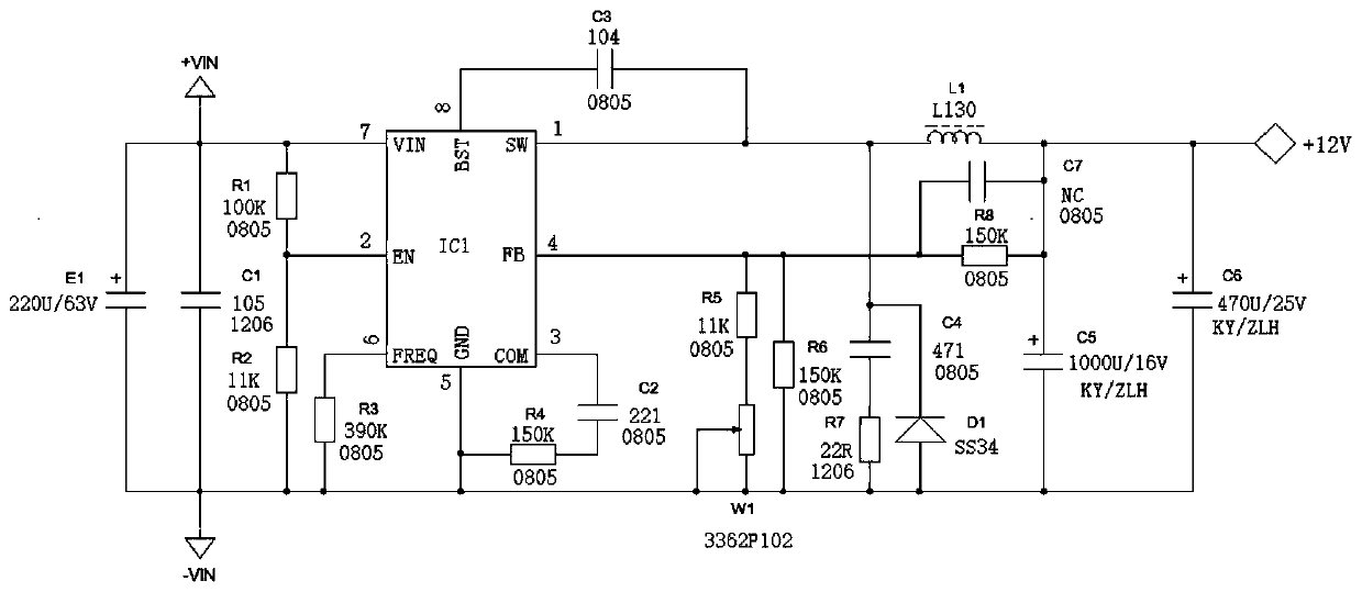
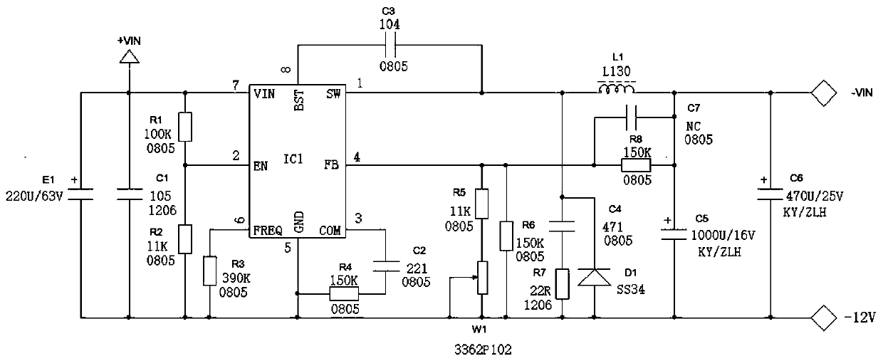
[0018] In the embodiment of the control circuit for positive and negative output in the present invention, the schematic diagram of the control circuit for positive and negative output is shown as figure 1 As shown, the schematic diagram of the negative output circuit is shown in figure 2 shown. Such as figure 1 with figure 2 As shown, the electrolytic capacitor E1, the first capacitor C1, the first resistor R1 and the second resistor R2 constitute the in...


PUM


Abstract

The invention discloses a control circuit for realizing positive and negative output. The circuit comprises an input circuit, a PWM control chip, a feedback circuit and a rectification output circuit.The input circuit comprises an electrolytic capacitor, a first capacitor, a first resistor and a second resistor. The feedback circuit comprises an eighth resistor, a seventh capacitor, a sixth resistor, a fifth resistor and a potentiometer; the rectification output circuit comprises a first inductor, a fifth capacitor, a sixth capacitor and a first diode. The positive electrode of the electrolytic capacitor is connected with one end of the first capacitor, one end of the first resistor and a VIN pin of the PWM control chip. The other end of the first resistor is connected with one end of thesecond resistor and a second pin of the PWM control chip, an SW pin of the PWM control chip is connected with a cathode of the first diode and one end of the first inductor, and an FB pin of the PWMcontrol chip is connected with one end of the fifth resistor and one end of the sixth resistor. The design and application are simple and reliable.

Description

technical field [0001] The invention relates to the field of control circuits, in particular to a control circuit for realizing positive and negative outputs. Background technique [0002] The BUCK circuit refers to a single-tube non-isolated DC conversion whose output is less than the voltage. The traditional BUCK circuit has different circuit controls for positive and negative outputs, and the design and layout are quite different, so they cannot be used universally. The voltage output by the simple BUCK circuit is unstable and will be disturbed by the load and the outside. When a PID controller is added to realize closed-loop control. The PWM modulation wave can be obtained through the sampling link, and then compared with the reference voltage, the feedback signal is obtained through the PID controller, and compared with the triangular wave, the modulated switching waveform is obtained, which is used as the switching signal, thereby realizing the closed-loop PID control...

Claims


Application Information

Patent Timeline
Patent Type & Authority Applications(China)
IPC IPC(8): H02M3/06
CPCH02M3/06
Inventor 龙锡炎
Owner 深圳市东圣源达科技有限公司
Learn More