Lifting device for building construction

A lifting device and construction technology, applied in the direction of lifting devices, lifting frames, lifting equipment safety devices, etc., can solve the problems of difficult installation, waste of manpower, low efficiency, etc., and achieve easy movement and installation, high practicability, and lifting wide range of effects

Inactive Publication Date: 2020-09-01
王侠
View PDF0 Cites 8 Cited by
  • Summary
  • Abstract
  • Description
  • Claims
  • Application Information

AI Technical Summary

Problems solved by technology

[0003] During the construction process, some small building construction objects need to be lifted from a low place to a high place. If only manual handling is used, it is not only inefficient, but also wastes manpower. Large-scale lifting equipment is not easy to move and difficult to install

Method used


Image

  • Lifting device for building construction
  • Lifting device for building construction
  • Lifting device for building construction

Examples


Embodiment 1

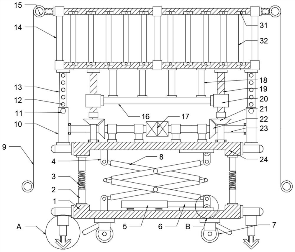
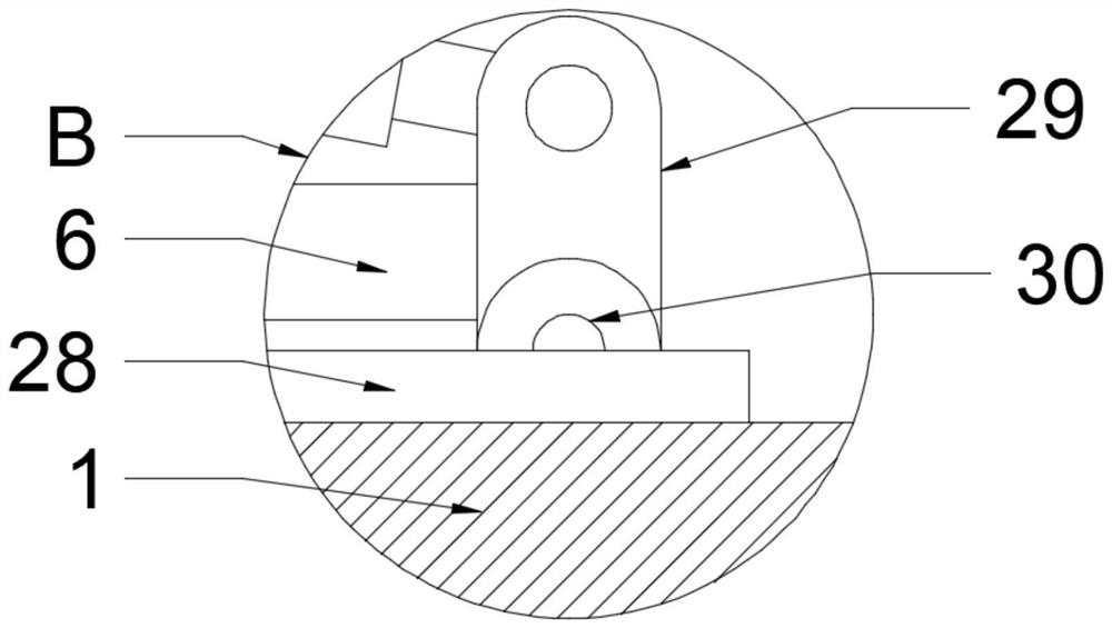
[0021] see Figure 1-3 , a lifting device for building construction, comprising a base 1 and a lifting platform 14, a support plate 24 is installed above the base 1, a cylinder 5 is fixedly installed on the upper surface of the base 1, and the cylinder 5 and the base 1 are fixedly connected by welding , the cylinder 5 is connected to the telescopic rod 6, the end of the telescopic rod 6 away from the cylinder 5 is fixedly connected to the movable seat 29, the bottom of the movable seat 29 is fixedly connected to the pulley 30, and the right side of the cylinder 5 is equipped with a chute 28, The chute 28 is welded on the upper surface of the base 1, the pulley 30 is installed in the chute 28, the pulley 30 can move left and right in the horizontal direction in the chute 28, and the symmetrical installation between the base 1 and the support plate 24 is movable. Seat 29, pulley 30 and chute 28, described movable seat 29 rotates and connects cross lifting rod 8, and fixed seat 4...

Embodiment 2

[0026] see Figure 1-4 , on the basis of Embodiment 1, in order to enable the lifting platform 14 to reach a higher height, the upper surface of the support plate 24 is symmetrically installed with a driving motor 17, and the output end of the driving motor 17 is fixedly connected to the rotating shaft 23, and the rotating shaft 23 is fixed Connect the bevel gear one 22, the left and right sides of the drive motor 17 are symmetrically installed screw mandrels 19, the screw mandrels 19 are rotationally connected with the support plate 24, the bevel gear two 21 is fixedly installed below the screw mandrel 19, the bevel gear one 22 meshes with bevel gear 2 21, and the moving seat 20 is installed on the surface of the screw mandrel 19, and the moving seat 20 on the left and right sides can move up and down in the vertical direction under the rotation of the screw mandrel 19, and the moving seat 20 on the left and right sides The support plate 16 is fixedly installed, and the upper...


PUM


Abstract

The invention discloses a lifting device for building construction and relates to the technical field of building construction equipment. The lifting device comprises a base and a lifting platform. Asupporting plate is installed above the base, an air cylinder is fixedly installed on the upper surface of the base and is connected with a telescopic rod, a movable seat is fixedly connected to the tail end of the side, away from the air cylinder, of the telescopic rod, a sliding wheel is fixedly connected tot he bottom of the movable seat, a sliding groove is formed in the right side of the aircylinder, the air cylinder pushes the telescopic rod to stretch and contract, the telescopic rod pushes the movable seat to move left and right in the horizontal direction, the sliding wheel slides left and right in the sliding groove, crossed lifting rods push the supporting plate to move up and down in the vertical direction, and initial lifting of the supporting plate is achieved; driving motors drive rotating shafts and first bevel gears to rotate, the first bevel gears drive second bevel gears and lead screws to rotate, the movable seats drives a bracket plate and connecting columns to move up and down in the vertical direction, and thus lifting of the lifting platform is achieved again. Building materials are conveyed to specified height, the lifting range is larger, and the equipment is convenient to move and install.

Description

technical field [0001] The invention relates to the technical field of building construction equipment, in particular to a lifting device for building construction. Background technique [0002] Building construction refers to the production activities in the implementation stage of engineering construction. It is the construction process of various buildings. It can also be said to be the process of turning various lines on the design drawings into physical objects at designated locations. It includes basic engineering construction. , main structure construction, roofing engineering construction, decoration engineering construction, etc., the place where the construction work is called the construction site. [0003] During the construction process, some small construction objects need to be lifted from a low place to a high place. If only manual handling is used, it is not only inefficient, but also wastes manpower. Large-scale lifting equipment is not easy to move and dif...

Claims


Application Information

Patent Timeline
Patent Type & Authority Applications(China)
IPC IPC(8): B66F11/04B66F7/06B66F7/08B66F7/14B66F7/28B66F17/00B66C23/48
CPCB66C23/48B66F7/0666B66F7/085B66F7/14B66F7/28B66F11/042B66F17/00B66F17/006
Inventor 王侠
Owner 王侠
Why Eureka
Try Eureka