Stranding device for steel wire rope

A technology for a steel wire rope and a wire crimping device is applied in the field of twisting devices, which can solve the problems of inconvenient disassembly and replacement of a pay-off reel and a take-up reel, affecting the production efficiency of the wire rope, and low forming efficiency of the wire rope, etc. High efficiency, easy disassembly and replacement

Inactive Publication Date: 2020-09-01
溧阳市华菱精工科技有限公司
View PDF7 Cites 6 Cited by
  • Summary
  • Abstract
  • Description
  • Claims
  • Application Information

AI Technical Summary

Problems solved by technology

[0002] At present, the common steel wire rope production process is roughly divided into stranding and plying. The steps are as follows: multiple steel wires are drawn out by multiple wire drawing machines, and the multiple steel wires enter the stranding machine and are twisted into a stranding rope. Multiple stranding machines The multi-strand ropes sent out, and the multi-strand ropes enter the rope closing machine to form steel wire ropes of different specifications and sizes. However, the current steel wire rope twisting device has many shortcomings, such as poor stability, low wire rope forming efficiency and strength. Not enough, it is inconvenient to disassemble and replace the pay-off reel and take-up reel of the wire rope twisting device, which seriously affects the production efficiency of the wire rope, so further improvement is needed

Method used


Image

  • Stranding device for steel wire rope
  • Stranding device for steel wire rope
  • Stranding device for steel wire rope

Examples


Embodiment 1

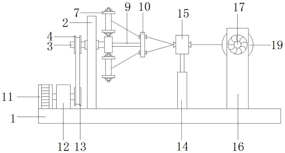
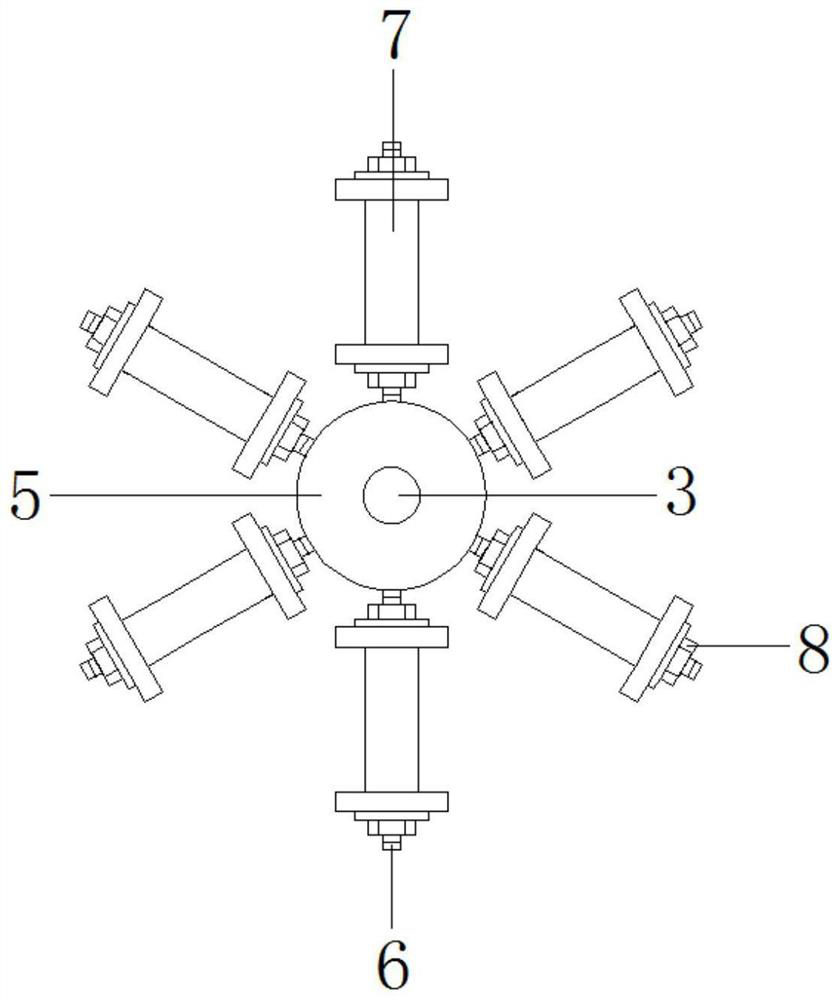
[0020] Such as Figure 1-Figure 4 As shown, the twisting device for steel wire rope provided by the present invention includes a base 1, a vertical plate 2 is fixedly arranged on the top of the base 1, and a pillar 3 is arranged on the top of the vertical plate 2 through a rotating shaft, and a fixed sleeve at one end of the pillar 3 is provided with a The other end of the moving wheel 4 is fixedly provided with a turntable 5, and the outside of the turntable 5 is equidistantly fixed with a first threaded rod 6, and the first threaded rod 6 is connected to the turntable 5 through a rotating shaft, and the outer side of the first threaded rod 6 is sleeved There is a thread reel 7, one side of the turntable 5 is fixedly provided with a rotating rod 9, one end of the rotating rod 9 is fixedly provided with a twisting disc 10, and the top of one side of the base 1 is fixedly provided with a first drive motor 11, and the first drive motor 11 drives The shaft end is fixedly connecte...

Embodiment 2

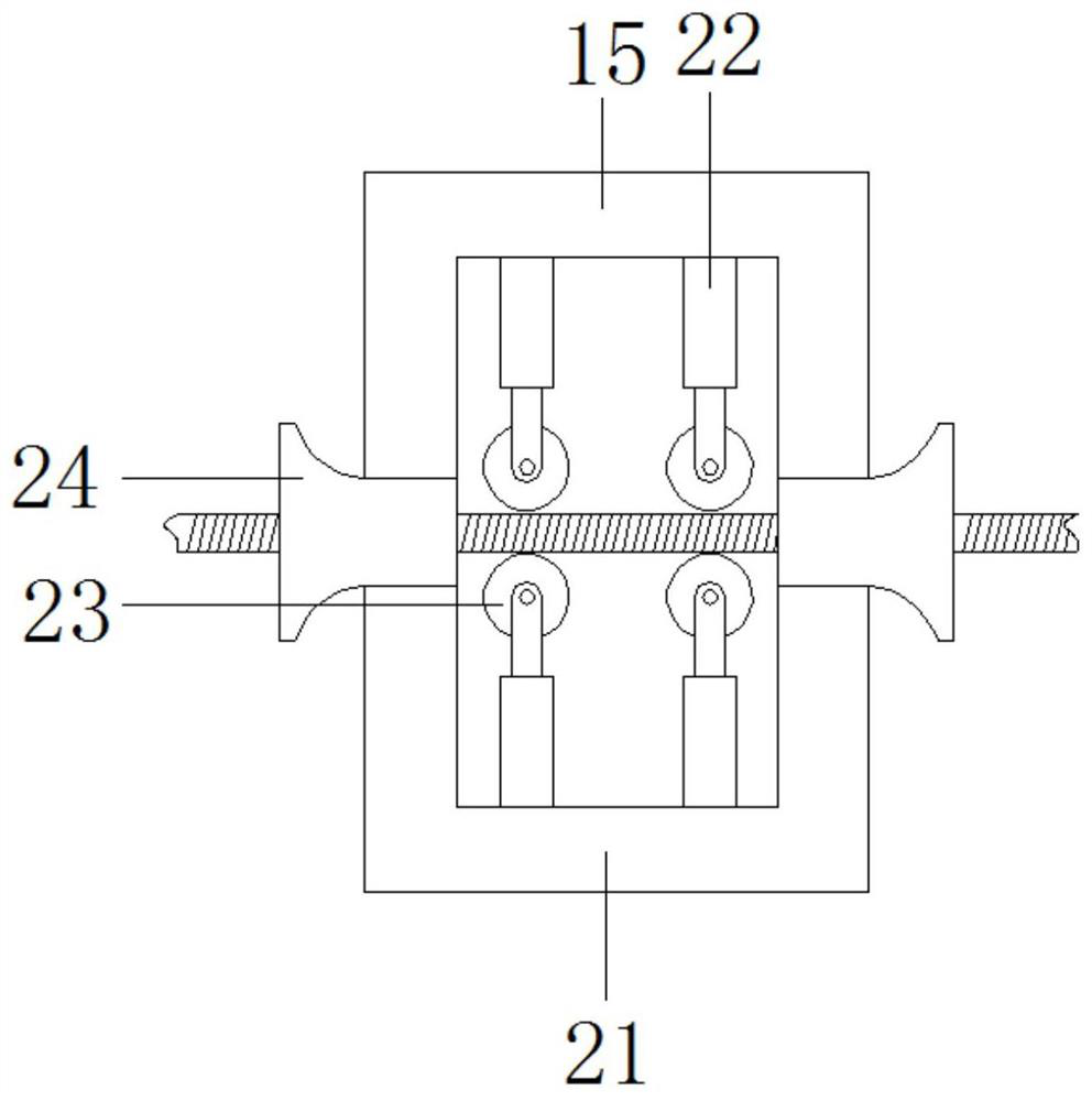
[0025] This embodiment 2 is based on embodiment 1, such as image 3 As shown, the wire crimping device 15 includes an outer shell 21, the top and bottom of the inner cavity of the outer shell 21 are symmetrically fixed with a hydraulic rod 22, the end of the hydraulic rod 22 is fixed with a crimping roller 23, and the two sides of the outer shell 21 are symmetrically provided with threading rods. port 24, and the threading port 24 is set as a funnel, the hydraulic rod 22 can control the lifting of the crimping roller 23, and the crimping roller 23 can integrate the steel wire rope passing through the middle part of the outer housing 21.

[0026] Working principle of the present invention: the first driving motor 11 can drive the driven wheel 4 to rotate through the driving wheel 13, and the driven wheel 4 can drive the turntable 5 and the twisting disk 10 to rotate synchronously through the pillar 3, and the steel wire on the branching reel 7 can be twisted. Wire rope is made,...


PUM


Abstract

The invention relates to a stranding device for a steel wire rope. The stranding device comprises a pedestal, a top part of the pedestal is fixedly provided with a vertical plate, the vertical plate is rotationally provided with a support column through a rotating shaft, one end of the support column is externally and fixedly sleeved with a driven wheel while the other end thereof is fixedly provided with a turntable, a first driving motor is arranged, and through the driving wheel, the first driving motor can drive the driven wheel to rotate, the driven wheel can drive the turntable and a stranding disk to rotate synchronously through the support column, steel wires on a wire separating reel can be stranded into the steel wire rope, and by arrangement of a wire pressing device, the steelwire rope can be integrated, and molding strength of the steel wire rope can be improved; and by arrangement of a second driving motor, the second driving motor can drive a take-up reel to rotate, thetake-up reel can take up and collect the steel wire rope processed well, the wire separating reel and the take-up reel are respectively locked and fixed through a first lock nut and a second lock nut, thus, the wire separating reel and the take-up reel can be detached and changed conveniently, and processing efficiency of the steel wire rope can be improved.

Description

technical field [0001] The invention relates to a twisting device for steel wire ropes, and belongs to the technical field of production process equipment for elevator steel wire ropes. Background technique [0002] At present, the common steel wire rope production process is roughly divided into stranding and plying. The steps are as follows: multiple steel wires are drawn out by multiple wire drawing machines, and the multiple steel wires enter the stranding machine and are twisted into a stranding rope. Multiple stranding machines The multi-strand ropes sent out, and the multi-strand ropes enter the rope closing machine to form steel wire ropes of different specifications and sizes. However, the current steel wire rope twisting device has many shortcomings, such as poor stability, low wire rope forming efficiency and strength. Not enough, it is inconvenient to disassemble and replace the pay-off reel and the take-up reel of the wire rope twisting device, which seriously a...

Claims


Application Information

Patent Timeline
Patent Type & Authority Applications(China)
IPC IPC(8): D07B3/04D07B7/02D07B7/06D07B7/10
CPCD07B3/04D07B7/027D07B7/06D07B7/10
Inventor 徐健黄超王迪崔影薛平陶蕾陈海华
Owner 溧阳市华菱精工科技有限公司
Why Eureka
Try Eureka