Magnetofluid bearing

A magnetic fluid and bearing technology, applied in the field of mechanical parts and equipment, can solve problems such as gap expansion, easy leakage loss, affecting the magnetic field strength, etc., and achieve the effect of preventing leakage

Pending Publication Date: 2020-09-01
黄尉欢
View PDF11 Cites 9 Cited by
  • Summary
  • Abstract
  • Description
  • Claims
  • Application Information

AI Technical Summary

Problems solved by technology

[0005] Magnetic fluid materials have both liquid fluidity and solid magnetic materials, and can be used in various fields; traditional sliding bearings have a greater load capacity than ball bearings, but because the lubricating grease inside them is easy to Leakage loss causes dry friction between the shaft and the bearing, causing greater damage, so it is generally used for low-speed bearings; while using magnetic fluid as the magnetic fluid bearing in contact with the lubricating medium, the magnetic fluid in it is affected by the magnetic field of the ring permanent magnet. An annular liquid "O" ring composed of magnetic fluid is formed in the gap between the inner surface of the bearing inner sleeve corresponding to the two ends of the block annular permanent magnet and the rotating shaft. Due to the existence of this "O" ring, the The lubricating surface of the sliding bearing always has a sufficient and uniform lubricating medium. The "O" ring can not only realize the lubricating effect, but also has stagnation due to the action of the magnetic field strength, and it is not easy to leak under normal temperature. Heat will inevitably be generated between the components and conducted between the components. On the one hand, it will affect the strength of the magnetic field. On the other hand, due to thermal expansion, the gap between the shaft and the bearing will expand, making the magnetic fluid in it more prone to free flow and leakage. Affect the subsequent transmission effect of the bearing

Method used


Image

  • Magnetofluid bearing
  • Magnetofluid bearing
  • Magnetofluid bearing

Examples


Embodiment Construction

[0024] The technical solutions in the embodiments of the present invention will be clearly and completely described below in conjunction with the drawings in the present invention. Apparently, the described embodiments are only some of the embodiments of the present invention, not all of them. Based on the embodiments of the present invention, all other embodiments obtained by persons of ordinary skill in the art without making creative efforts belong to the protection scope of the present invention. If the words "up", "down", "left" and "right" appear in the following, it only means that they are consistent with the directions of up, down, left and right in the drawings themselves, and do not limit the structure.

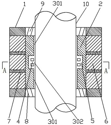
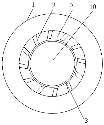
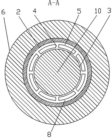
[0025] Such as Figure 1~3 A magnetic fluid bearing shown includes a bearing outer ring 1, a bearing inner ring 2 and an annular permanent magnet 6; the inner side wall of the bearing inner ring 2 is in sliding fit with the rotating shaft 10 to be carried, so that ...


PUM


Abstract

The invention discloses a magnetofluid bearing, and belongs to the field of mechanical part equipment. According to the magnetofluid bearing, an annularly cavity is formed in the position, close to the middle, in an inner ring of the bearing, and communicates with a magnetofluid clearance where magnetofluid is located through a plurality of evenly arranged communicating holes; due to the fact thatwhen a rotary shaft of a middle workpiece rotates, the magnetofluid in contact with the workpiece can be driven to rotate, part of the magnetofluid at the position, close to the annular cavity, of the middle area flows to the annular cavity through the communicating holes under the action of centrifugal force and flows along the annular cavity; and therefore the magnetofluid on the outer side ofthe clearance flows to the middle area, the magnetofluid on the two sides is prevented from moving outwards, and turbofans are arranged at the positions, at the upper end and the lower end of the inner ring of the bearing, of the inner side of the inner ring of the bearing correspondingly; and when the rotary shaft rotates, air near blades of the turbofans flows towards the clearance of the magnetofluid and the inner ring of the bearing, on one hand, a heat dissipation function is achieved, and on the other hand, the magnetofluid inside is prevented from moving outwards, and the effect of preventing leakage is achieved.

Description

technical field [0001] The invention belongs to the field of mechanical parts and equipment, and in particular relates to a magnetic fluid bearing of the bearing type. Background technique [0002] Magnetic fluid, also known as magnetic liquid, ferrofluid or ferrofluid, is a new type of functional material, which has both the fluidity of liquid and the magnetism of solid magnetic materials. It is a stable colloidal liquid composed of magnetic solid particles with a diameter of nanometers (less than 10 nanometers), a base carrier liquid (also called a medium) and a surfactant. The fluid has no magnetic attraction when it is static, and it shows magnetism when an external magnetic field is applied. Because of this, it has a wide range of applications in practice and has high academic value in theory. The magnetic fluid produced with nano-metal and alloy powder has excellent performance, and can be widely used in various harsh conditions of magnetic fluid sealing, shock absorp...

Claims


Application Information

Patent Timeline
Patent Type & Authority Applications(China)
IPC IPC(8): F16C32/04F16C33/10F16C37/00
CPCF16C32/0408F16C33/106F16C37/005F16C2210/06
Inventor 黄尉欢
Owner 黄尉欢
Why Eureka
Try Eureka