
Granular material throwing device

A throwing device and granular technology, which is applied in fertilization devices, fertilizer distributors, applications, etc., can solve the problems of waste of raw materials, inability to accurately scatter particles, and limited scatter efficiency, and achieve the effect of increasing efficiency

Inactive Publication Date: 2020-09-04
吴永化
View PDF0 Cites 1 Cited by
  • Summary
  • Abstract
  • Description
  • Claims
  • Application Information

AI Technical Summary

Problems solved by technology

[0004] In view of the deficiencies in the prior art, the purpose of the present invention is to provide a granular material spreading device to solve the problem that in the existing process of spreading granular fertilizers, feeding and discharging are synchronous, and when adding fertilizer raw materials , the baffle needs to be opened first, and the particulate material will fall directly along the track, which will easily cause a part of the particulate matter to be accurately thrown to the target area, and the throwing efficiency is limited and the waste of raw materials will be caused.

Method used


Image

  • Granular material throwing device
  • Granular material throwing device
  • Granular material throwing device

Examples


no. 1 example

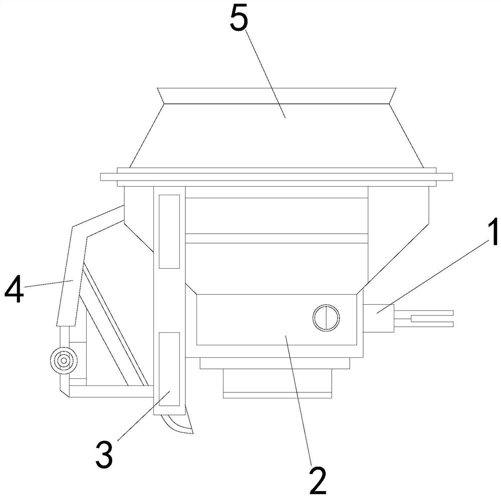
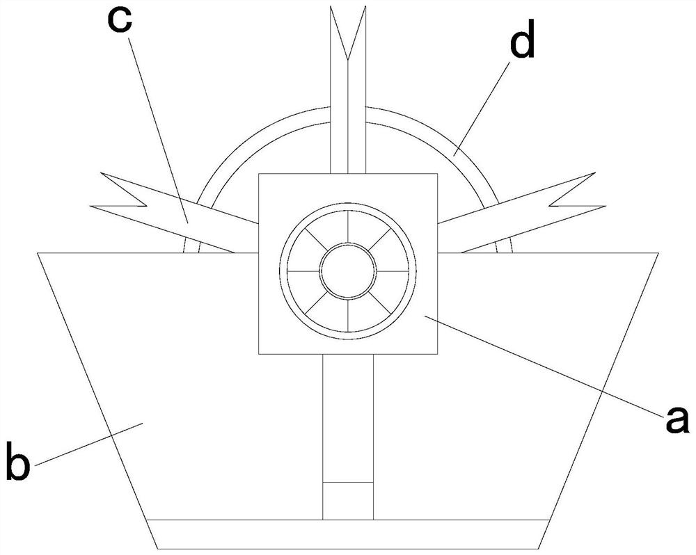
[0025] see Figure 1-Figure 2 , the present invention provides a technical solution for a granular material throwing device: its structure includes: a throwing body 1, a power device 2, a moving matching seat 3, a connecting frame 4, and a raw material bin 5, and the raw material bin 5 is installed on the power device 2 Above and locked with the power device 2, the right side of the power device 2 is provided with a throwing body 1, the throwing body 1 is movably connected with the power device 2, and the left end of the power device 2 is provided with a moving matching seat 3, and the moving The matching seat 3 is locked with the power device 2, and the left side of the moving matching seat 3 is provided with a connecting frame 4, and the connecting frame 4 is threadedly connected with the moving matching seat 3, and the throwing machine body 1 includes a movable leaking cylinder device a , baffle plate b, throwing frame c, fixed frame d, the movable leakage tube device a is ...

no. 2 example

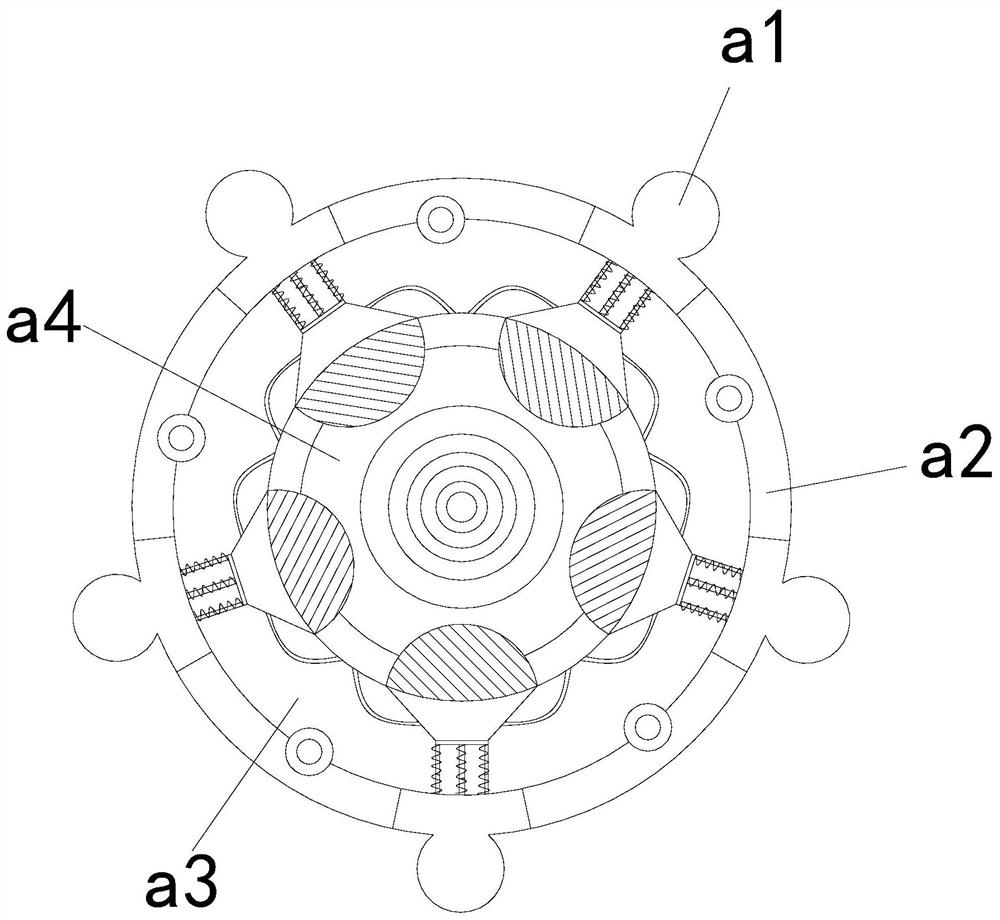
[0028] see Figure 3-Figure 5 , the present invention provides a technical solution for a granular material throwing device: its structure includes: the movable funnel device a includes a self-opening block device a1, an assembly groove a2, a connecting funnel a3, and a feeding groove pipe a4; A self-opening block device a1 is provided on the periphery of the trough pipe a4, and the self-opening block device a1 is closely matched with the feeding trough pipe a4, and a connecting funnel a3 is provided under the self-opening block device a1 and is connected to the connecting funnel. a3 is fastened, and the outside of the connecting funnel a3 is provided with an assembly groove a2.

[0029] The self-opening block device a1 includes a connection spring a11, a counterweight a12, a reset rope a13, and a groove stopper a14. The counterweight a12 is installed at the end of the connection spring a11 and is fastened with the connection spring a11. The inner side of the connection sprin...


PUM


Abstract

The invention discloses a granular material throwing device. The granular material throwing device structurally comprises a throwing machine body, a power device, a movable matching base, a connectionmachine frame and a raw material warehouse. When equipment is used, due to an arranged throwing mechanism, the granular material throwing device in the invention can avoid the disadvantages as follows: in the process of throwing a granular fertilizer, charging and discharging are synchronous; when raw materials of the fertilizer are to be added, a baffle needs to be opened at first; granular rawmaterial can directly fall off along a track; partial granular matters cannot be precisely threw into a target area; the throwing efficiency is limited; and furthermore, waste of raw materials is easily caused. Due to mutual matching between a movable leakage cylinder device and the power device, when the lower end of the equipment rotates, a blanking channel can be automatically opened or closedaccording to the centrifugal action itself; the process is relatively convenient; fertilizers can be precisely threw into the target area; unnecessary waste is avoided; simultaneously, raw materials also can be added in advance; and the throwing efficiency is increased through movable matching of a throwing frame.

Description

technical field [0001] The invention is a granular material throwing device, which belongs to the field of throwing machine equipment. Background technique [0002] The spreader is used for high-quality, large-area, high-efficiency sowing operations. It can be easily used for spreading base fertilizer before plowing, sowing after plowing and grassland. It is an indispensable part of the development of existing agricultural production. [0003] The existing technology has the following disadvantages: in the process of throwing granular fertilizers, feeding and discharging are synchronized. When adding fertilizer raw materials, it is necessary to open the baffle first, and the granular raw materials will fall directly along the track. If it falls, it is easy to cause a part of the particles to be unable to be accurately scattered to the target area, and the scattering efficiency is limited and the waste of raw materials is caused. Contents of the invention [0004] In view ...

Claims


Application Information

Patent Timeline
IPC IPC(8): A01C15/06
CPCA01C15/06
Inventor 吴永化
Owner 吴永化
Features
  • Generate Ideas
  • Intellectual Property
  • Life Sciences
  • Materials
  • Tech Scout
  • Unparalleled Data Quality
  • Higher Quality Content
  • 60% Fewer Hallucinations
Learn More