Flue gas inlet pretreatment device
A technology of pretreatment device and air inlet, which is used in transportation and packaging, separation of dispersed particles, chemical instruments and methods, etc. The effect of blocking, reducing production costs, and ensuring the entry rate
- Summary
- Abstract
- Description
- Claims
- Application Information
AI Technical Summary
Problems solved by technology
Method used
Image
Examples
Embodiment 1
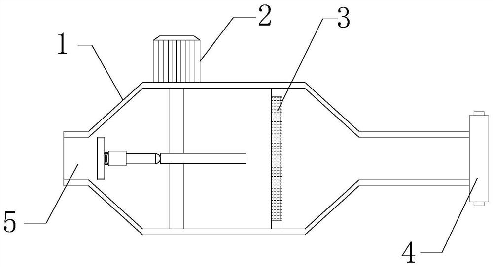
[0023] see figure 1 and figure 2 , a flue gas inlet pretreatment device, comprising an air inlet passage 1 and an air inlet 5, the outlet end of the air inlet passage 1 communicates with the inlet end of the cooling tower through a flange 4, and the air inlet The port 5 is arranged at the intake end of the intake passage 1; it also includes a first anti-blocking mechanism 2, which is used to dredge the intake port 5 and prevent the intake port 5 from being blocked.
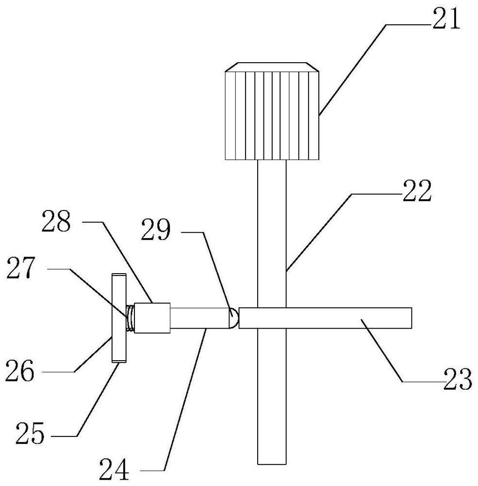
[0024] The first anti-blocking mechanism 2 includes a first motor 21, a first rotating shaft 22, a cam 23, a guide sleeve 28, a transmission rod 24, a transmission ball 29, a piston plate 26 and a spring 27, and the first motor 21 is welded on the The side wall of the air passage 1, the first rotating shaft 22 is rotatably connected inside the air intake passage 1, and the first rotating shaft 22 is fixedly connected to the output end of the first motor 21, and the cam 23 is fixed on the first rotating shaft 22,...
Embodiment 2
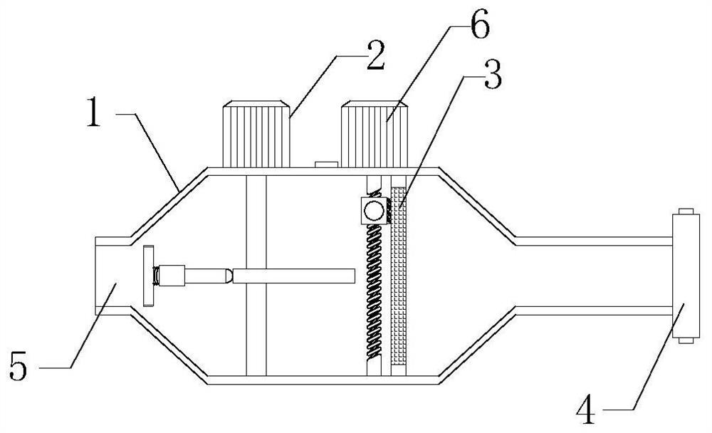
[0028] As a preferred solution of Embodiment 1, please refer to image 3 and Figure 4 , also includes a filter 3 , the filter 3 is arranged inside the air intake channel 1 and is located on the side of the first anti-blocking mechanism 2 away from the air inlet 5 .
[0029] It also includes a second anti-clogging mechanism 6, which includes a second motor 61, a second rotating shaft 62, a screw mandrel 66, a slider 65, a ball nut pair 64 and a cleaning brush 67, and the second motor 61 is welded on the side wall of the air intake channel 1, the second rotating shaft 62 is rotatably connected inside the air intake channel 1, and the second rotating shaft 62 is fixedly connected with the output end of the second motor 61, and the screw rod 66 is connected with the second rotating shaft 62 is coaxially fixed and rotatably connected inside the intake passage 1, the slider 65 is slidingly connected inside the intake passage 1, the ball nut pair 64 is arranged inside the slider 65...
Embodiment 3
[0032] As a preferred solution of Embodiment 1 or Embodiment 2, please refer to Figure 5, also includes a transmission mechanism 7, the transmission mechanism 7 includes a transmission shaft 72, a synchronous belt 71, a missing tooth gear 75, a transmission gear 74 and a torsion spring 73, and the transmission shaft 72 is rotatably connected to the inside of the intake passage 1, and the The transmission shaft 72 is connected to the first rotating shaft 22 through a synchronous belt 71. The tooth-missing gear 75 is arranged on the transmission shaft 72, the transmission gear 74 is arranged on the shaft, and the transmission gear 74 is meshed with the tooth-missing gear 75. The torsion spring 73 is disposed on the inner wall of the intake passage 1 , and the torsion spring 73 is sheathed outside the second rotating shaft 62 , and the inner wall of the torsion spring 73 is closely connected with the annular side of the second rotating shaft 62 .
[0033] Work process: run the f...
PUM
 Abstract
Description
Claims
Application Information
 - R&D
- Intellectual Property
- Life Sciences
- Materials
- Tech Scout
- Unparalleled Data Quality
- Higher Quality Content
- 60% Fewer Hallucinations
Browse by: Latest US Patents, China's latest patents, Technical Efficacy Thesaurus, Application Domain, Technology Topic, Popular Technical Reports.
© 2025 PatSnap. All rights reserved.Legal|Privacy policy|Modern Slavery Act Transparency Statement|Sitemap|About US| Contact US: help@patsnap.com


