Worm gear and worm transmission structure, worm gear and worm speed reducer and speed reduction motor

A technology of worm reducer and worm gear, which is applied in the field of worm gear reducer, gear motor, and worm gear transmission structure, and can solve problems such as difficulty in starting the gear motor.

Pending Publication Date: 2020-09-04
衢州一诚工业设计有限公司
View PDF5 Cites 2 Cited by
  • Summary
  • Abstract
  • Description
  • Claims
  • Application Information

AI Technical Summary

Problems solved by technology

[0004] Aiming at the above-mentioned deficiencies or defects in the prior art, the present invention provides a worm gear transmission structure to solve the problem of difficulty in starting the geared motor

Method used


Image

  • Worm gear and worm transmission structure, worm gear and worm speed reducer and speed reduction motor
  • Worm gear and worm transmission structure, worm gear and worm speed reducer and speed reduction motor
  • Worm gear and worm transmission structure, worm gear and worm speed reducer and speed reduction motor

Examples


Embodiment Construction

[0049] Specific embodiments of the present invention will be described in detail below. It should be understood that the specific embodiments described here are only used to illustrate and explain the present invention, and are not intended to limit the present invention.

[0050] In the present invention, unless stated otherwise, the used orientation words such as "upper and lower" usually refer to the orientation in the state of assembly and use. "Inner and outer" refer to inner and outer relative to the outline of each component itself.

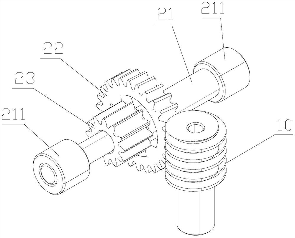
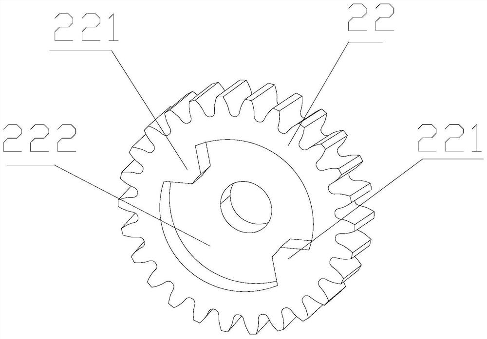
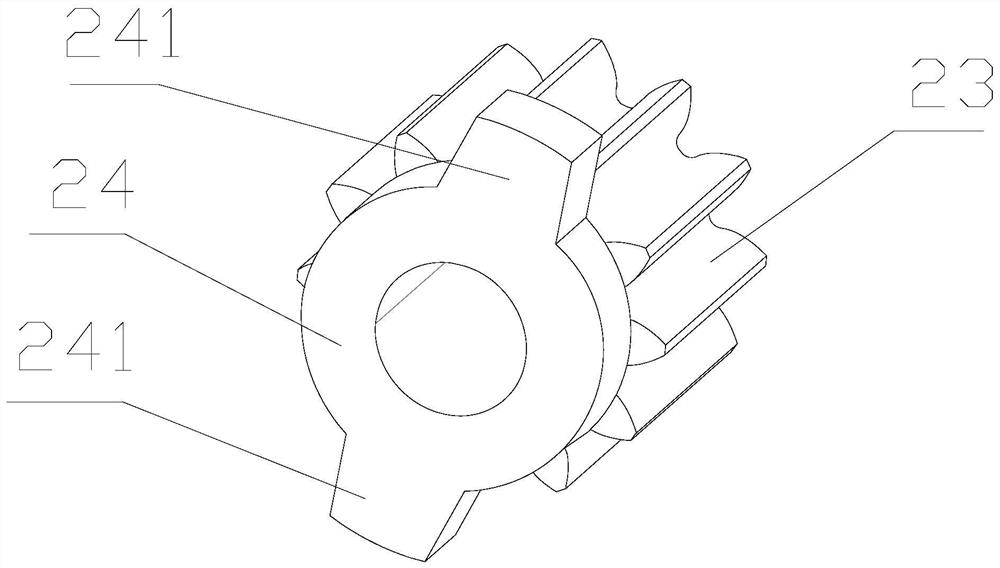
[0051] The first aspect provided in the present invention provides a worm gear transmission structure, such as figure 1 As shown, the worm gear transmission structure includes a worm 10 and a worm gear assembly; the worm gear assembly includes a worm shaft 21, a worm wheel 22 and a gear 23 sleeved on the worm shaft 21, and is used to delay the worm wheel 22 and the worm gear assembly. The engagement delay mechanism for the engagement of ...


PUM


Abstract

The invention relates to the field of speed reducers, and discloses a worm gear and worm transmission structure, a worm gear and worm speed reducer and a speed reduction motor. The worm gear and wormtransmission structure comprises a worm and a worm gear assembly. The worm gear assembly comprises a worm gear shaft, a worm gear, a gear, and a meshing delaying mechanism for delaying meshing of theworm gear and the gear, and the worm gear and the gear are arranged on the worm gear shaft in a sleeving mode. According to the technical scheme, based on the arrangement of the meshing delaying mechanism, after the worm drives the worm gear, the worm gear cannot immediately drive the gear to rotate, a certain time difference exists between the motion of the worm gear and the motion of the gear, the angular momentum of the worm gear can be improved by utilizing the time difference, and the angular momentum can be converted into impulse acting on the gear, so that the aim of overcoming the maximum static friction force in a system is achieved, and the problem of difficulty in starting the speed reduction motor is solved.

Description

technical field [0001] The invention relates to the field of reducers, in particular to a worm gear transmission structure, a worm gear reducer and a geared motor. Background technique [0002] The worm gear reducer uses the rotation of the worm to drive the worm gear to rotate, so as to achieve the effect of reducing the speed and increasing the torque. The worm gear reducer plays the role of matching the speed and transmitting torque between the prime mover and the working machine or the actuator. The geared motor is a combination of a reducer and a motor. The motor shaft is directly connected to the reducer, and the speed is output through the output shaft of the reducer. [0003] The geared motor needs to overcome the static friction and load torque in the system when starting. Since the static friction is larger than the dynamic friction and the load torque remains unchanged, when the load torque is large, the main shaft of the geared motor will Unable to overcome the ...

Claims


Application Information

Patent Timeline
Patent Type & Authority Applications(China)
IPC IPC(8): F16H1/22F16H57/023F16H57/039F16D1/06H02K7/116
CPCF16D1/06F16H1/222F16H57/023F16H57/039H02K7/1166
Inventor 冯云和
Owner 衢州一诚工业设计有限公司
Why Eureka
Try Eureka