
Binding wire supply device of electric power optical cable erecting machine

A technology for bundling and supplying wires, which is applied in the direction of optical fiber/cable installation, optics, light guide, etc. It can solve the problem that there is no tension in the bundling wire or the tension cannot be adjusted, which affects the quality and safety of optical cable construction, and it is difficult to ensure that the set parts do not fall off, etc. problems, to achieve the effect of avoiding falling accidents of machine parts from high altitudes, improving the level of safe construction, and simple loading and binding lines

Pending Publication Date: 2020-09-04
STATE GRID CORP OF CHINA +2
View PDF0 Cites 0 Cited by
  • Summary
  • Abstract
  • Description
  • Claims
  • Application Information

AI Technical Summary

Problems solved by technology

The original bundled wire supply device of the power optical cable erection machine still has the following defects after practical application inspection. One is that the wire supply disk body is not equipped with a safety stopper. Under the action of centrifugal force, it is difficult to ensure that the set parts will not fall off. Once a part falls, it will cause damage, and even cause serious accidents such as injuries to ground operators.
The second is that when the binding wire is pulled and rotated, the wire supply disc body is not equipped with damping parts, even if some damping parts are installed, the damping force cannot be adjusted, so that the binding wire has no tension or the tension cannot be adjusted, and the binding result is either too tight or too loose , which seriously affects the quality and safety of optical cable construction

Method used


Image

  • Binding wire supply device of electric power optical cable erecting machine
  • Binding wire supply device of electric power optical cable erecting machine
  • Binding wire supply device of electric power optical cable erecting machine

Examples


Embodiment Construction

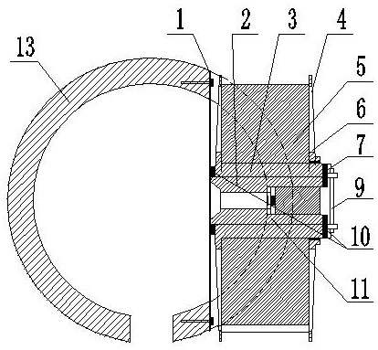
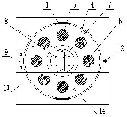
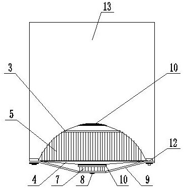
[0026] The implementation of the binding wire supply device of the power optical cable erecting machine will be further described in detail below in conjunction with the accompanying drawings (see Figure 1-18 ):

[0027] The bundled wire supply device of the power optical cable erecting machine consists of a base mounting plate 1, a base shaft 2, a wire supply disk body 3, a wire supply disk cover 4, a binding wire 5, a weight reduction hole 6, a pressure blocking cover 7, and male and female clamping positions. 8. A safety stopper 9, a damper 10, a base shaft threaded hole 11, a movable fixing device 12, and a rotating cylinder 13 are formed; the pressure blocking cover 7 is integrally made with a screw, and the diameter of the screw of the pressure blocking cover 7 is smaller than that of the base The diameter of the shaft threaded hole 11; the base mounting plate 1, one end of the safety stopper 9, and the movable fixing device 12 are installed on the rotating cylinder 13....


PUM


Abstract

The invention relates to a binding wire supply device of an electric power optical cable erecting machine, and belongs to the technical field of electric power optical cable construction tools. The device is composed of a base installation plate, a base shaft, a safety blocking piece, a damping piece and the like, wherein the base shaft is fixedly installed on the base installation plate, the baseshaft is sleeved with a wire supply disc body, the wire supply disc body is filled with binding wires, and the wire supply disc body is provided with a wire supply disc cover; a base shaft threaded hole formed in one end of the base shaft is provided with a pressing and blocking cover through a screw rod of the pressing and blocking cover, and a damping piece is arranged between the base mountingplate and the wire supply disc body or between the wire supply disc body and the pressing and blocking cover; the pressing blocking cover and the safety blocking piece are clamped and positioned through the male clamping position and the female clamping position, one end of the safety blocking piece is fixedly installed on the rotating cylinder, the other end of the safety blocking piece is movably connected with the rotating cylinder through the movable fixing device, and the movable fixing device controls the safety blocking piece to be opened or closed. The wire supply disc body and the wire supply disc cover form a wire supply disc. Filling and binding wires are simple, damping force adjustment is flexible, optical cable construction quality is guaranteed, high-altitude falling of machine parts is prevented, and use is safe and reliable.

Description

technical field [0001] The invention relates to a bundled wire supply device of an electric optical cable erecting machine, which belongs to the technical field of electric optical cable construction tools. Background technique [0002] Optical cable construction is inseparable from the optical cable erection machine, and the bundled wire supply device is an important part of the optical cable erection machine. The original bundled wire supply device of the power optical cable erection machine still has the following defects after practical application inspection. First, the wire supply disk body is not equipped with a safety stopper. When the wire supply device is under the action of centrifugal force, it is difficult to ensure that the set parts do not fall off. Once a part falls, it will cause damage, and even cause serious accidents such as injuries to ground operators. The second is that when the binding wire is pulled and rotated, the wire supply disc body is not equi...

Claims


Application Information

Patent Timeline
Patent Type & Authority Applications(China)
IPC IPC(8): G02B6/48
CPCG02B6/483
Inventor 王甘雨郭泓林郭殊郢黄薇罗功伟陈璇江浩李颖邓翔李涛
Owner STATE GRID CORP OF CHINA
Learn More