Wiring terminal

A terminal and cable technology, applied in the direction of connection, clamping/spring connection, line/collector components, etc., can solve the problems of inconvenient cable cutting, loose cable ends, poor contact, etc., and improve installation Efficiency, stable current output, and easy installation

Active Publication Date: 2020-09-04
北京北科集源电子科技有限公司
View PDF6 Cites 3 Cited by
  • Summary
  • Abstract
  • Description
  • Claims
  • Application Information

AI Technical Summary

Problems solved by technology

[0004] In order to make up for the deficiencies of the existing technology and solve the problems of inconvenient cable cutting and the traditional wiring method of winding the cable end on the terminal, it is easy to cause the cable end to loosen and cause poor contact. The present invention proposes a terminal

Method used


Image

  • Wiring terminal
  • Wiring terminal
  • Wiring terminal

Examples


Embodiment approach

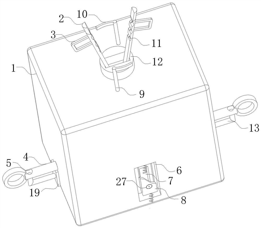
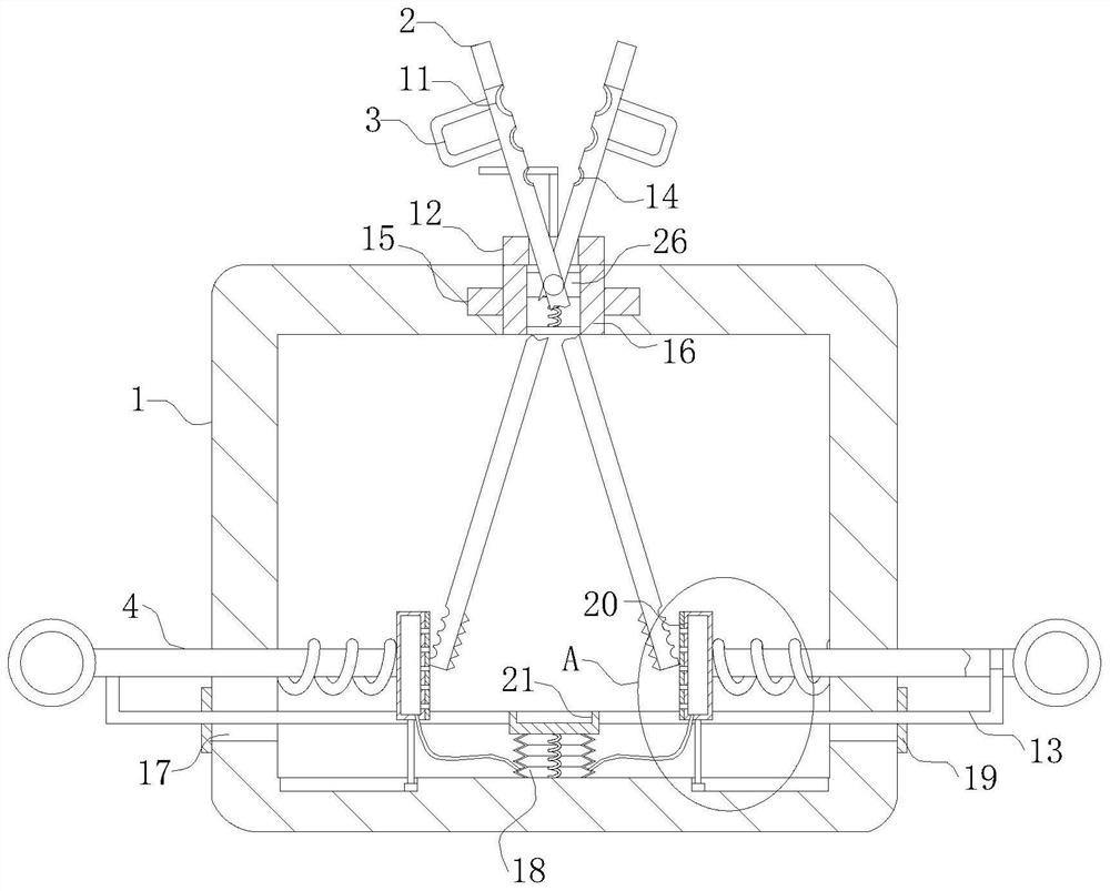
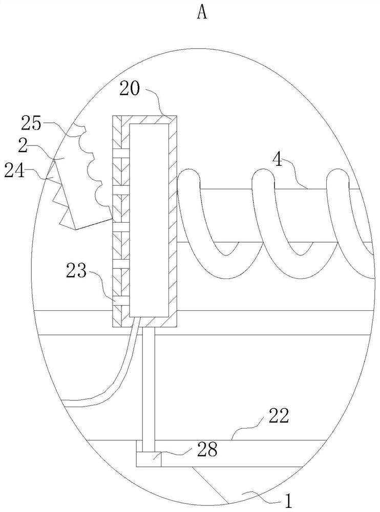
[0025] As an embodiment of the present invention, the clamping device includes a movable rod 4 and a pressing plate 20; the number of the pressing plates 20 is two, and two groups of the pressing plates 20 are respectively located Both sides; the pressing plate 20 is a semicircular arc-shaped plate, and the inner wall of the pressing plate 20 is glued with a rubber anti-skid pad; the outer wall of the pressing plate 20 is fixedly connected with one end of the movable rod 4; the movable rod The other end of 4 protrudes from the side wall of the housing 1 and is fixedly connected with the pull ring; the movable rod 4 is sleeved with a spring between the inner wall of the housing 1 and the pressing plate 20; the pressing plate 20 The bottom end is fixed with a limit slider 28 through a joint bar; the limit slider 28 is slidably connected with the limit chute 22 at the bottom of the housing 1; during work, when the pull ring is pulled to the outside of the housing 1 , the pressing...


PUM


Abstract

The invention belongs to the technical field of wiring terminals, and particularly relates to a wiring terminal which comprises a shell, an output rod, a lantern ring, a mounting pipe and a clamping device. The mounting pipe is arranged in a circular through hole in the center of the top of the shell; an annular sliding plate fixedly arranged at the outer edge of the mounting pipe is in sliding connection with an annular sliding groove in the inner wall of the circular through hole. A rectangular through hole is formed in the mounting pipe; a rectangular sliding groove is formed in the inner wall of the mounting pipe; the bottom of a rectangular sliding block is fixedly connected with the bottom of the rectangular sliding groove through a spring. A pin shaft is fixedly arranged on the rectangular sliding block; two output rods which are mutually symmetrical and crossed are movably arranged on the pin shaft through torsional springs; the two output rods are of semi-cylindrical structures respectively, and the curved surfaces of the two output rods deviate from each other. The top end of each output rod extends out of the top of the shell; and a handle is fixedly arranged at the edgeof the output rod and located above the lantern ring. Connection between the cable and the output rods is quite firm, current output is more stable, and meanwhile a cable insulating sleeve can be cut.

Description

technical field [0001] The invention belongs to the technical field of connection terminals, in particular to a connection terminal. Background technique [0002] Terminal block is an accessory product used to realize electrical connection, which is industrially divided into the category of connectors. With the increasing degree of industrial automation and stricter and more precise industrial control requirements, the amount of terminal blocks is gradually increasing. With the development of the electronics industry, the use of terminal blocks is increasing, and there are more and more types. Terminal blocks are used to connect wires, which can be applied to single-strand or multi-strand copper wires, and are an important part of wire connection. [0003] Before the connection between the cable and the conductor, the insulating layer on the surface of the cable needs to be stripped off. In the prior art, a vise is mostly used for stripping, so there will be disadvantages:...

Claims


Application Information

Patent Timeline
IPC IPC(8): H01R4/14H01R4/28H01R43/28B08B5/02
CPCB08B5/02H01R4/14H01R4/28H01R43/28
Inventor 韩振华高永航
Owner 北京北科集源电子科技有限公司
Why Eureka
Try Eureka