
Brake device and power assembly

A technology for braking devices and power components, applied in electric components, electromechanical devices, electrical components, etc., can solve the problems of easy generation of heat and dust, small braking torque, increase the volume of power components, etc., and achieve high braking reliability. , The effect of large braking torque and volume saving

Active Publication Date: 2020-09-04
NIDEC CORP
View PDF30 Cites 0 Cited by
  • Summary
  • Abstract
  • Description
  • Claims
  • Application Information

AI Technical Summary

Problems solved by technology

[0006] The inventors of the present application have found that the above two methods of the existing braking device have certain defects, for example, for the method using friction force, the braking torque is small, and heat and dust are easily generated during the braking process. , has adverse effects on the operation of the motor. If this effect is to be reduced, the braking device needs to be placed outside the motor, but this will increase the volume of the power assembly; for the method of using the locking mechanism, if the structure of ratchet and pawl is adopted , you need to set two sets of ratchets and pawls to achieve two-way locking. The braking device is more complicated. If the structure of screw and gear is used, it cannot be installed inside the motor due to problems such as reduction ratio and space.

Method used


Image

  • Brake device and power assembly
  • Brake device and power assembly
  • Brake device and power assembly

Examples


Embodiment 1

[0041] Embodiment 1 of the present application provides a brake device.

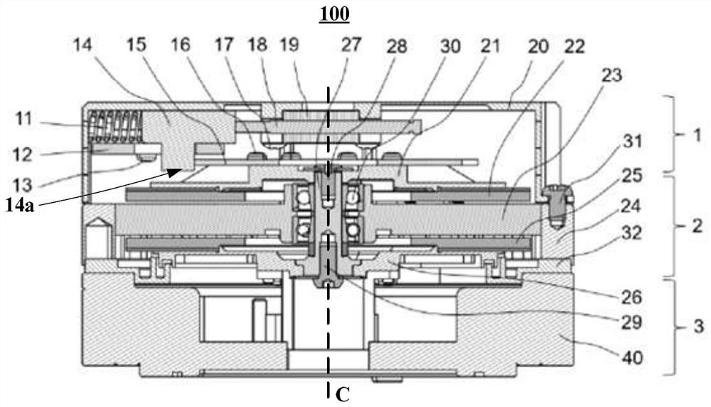
[0042] figure 1 It is a schematic diagram of the braking device of this embodiment installed on the motor and the braking device is in the braking position. Such as figure 1 As shown, the braking device 1 can be installed on the motor 2, and when the braking device 1 is in the braking position, the braking device 1 can brake the motor 2.

[0043] Such as figure 1 As shown, the motor 2 may be an axial flux motor, wherein the motor 2 may have: a rotating shaft 27 rotating around a central axis C; a first rotor 22 arranged radially outside the rotating shaft 27, the first rotor 22 is It can be a magnet, which generates axial magnetic flux; a stator 23 arranged on one axial side of the first rotor 22, for example, the stator 23 is arranged on the front side of the first rotor 22; The first rotor disk 21 on the other axial side of the stator 23, and the first rotor 22 is fixedly mounted on the first rotor...

Embodiment 2

[0075] Embodiment 2 of the present application provides a power assembly, which has the braking device described in Embodiment 1. Since the structure of the braking device has been described in detail in Embodiment 1, its content is incorporated here, and the description is omitted here.

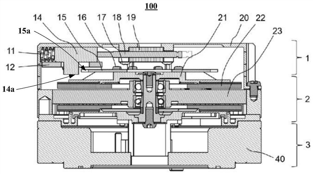
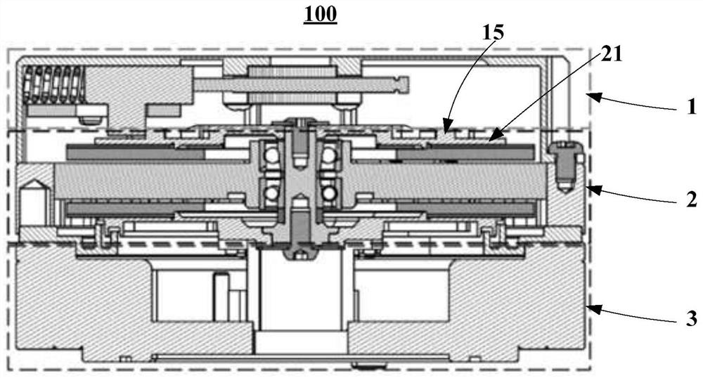
[0076] In this embodiment, the cross-sectional view of the power assembly 100 can be as follows figure 1 , figure 2 , image 3 , Figure 8 or Figure 9 shown. The power assembly 100 may have a braking device 1 and a motor 2 , wherein the braking device 1 is used to brake the motor 2 .

[0077] In this embodiment, the power assembly 100 may also have a speed reduction device 3 , and the speed reduction device 3 may be disposed on a side of the stator 23 away from the first rotor 22 in the axial direction. Wherein, the speed reduction device 3 is connected with the output end of the rotating shaft 27 of the motor 2, and the speed reducing device 3 transmits the power of the rotating sha...


PUM


Abstract

The embodiment of the invention provides a brake device and a power assembly. The brake device (1) is provided with: a brake disc (15) arranged on the side, away from the axial direction of a stator,of a first rotor disc (21) of a motor; a brake block (14) disposed on one side, away from the axial direction of a stator, of the brake disc (15); an elastic member (11) disposed on the outside in theradial direction of the brake block (14); a sliding block (18) disposed on the inner side in the radial direction of the brake block (14) and connected to the brake block (14); and an electromagneticvalve main body (19) arranged on the periphery of the sliding block (18) in a sleeving mode, wherein the brake block (14) is provided with a protruding part (14a) protruding towards the brake disc (15) in the axial direction, and when the brake device conducts braking, the protruding part (14a) of the brake block is meshed with the brake disc (15). According to the embodiment of the invention, the brake device is simple in structure, large in braking torque and high in braking reliability, and the size occupied by the brake device can be reduced.

Description

technical field [0001] The present application relates to the electromechanical field, in particular to a braking device and a power assembly. Background technique [0002] In automation equipment, power components are usually used to provide driving force for the movable parts of the equipment. The power assembly can have a motor and a reduction device, wherein the reduction device can be connected to the output end of the motor's rotating shaft, and the reduction device can transmit the power of the motor's rotating shaft through its internal gear and other transmission components, and output the power from the output shaft. For power, the rotational speed of the output shaft of the speed reduction device may be lower than the rotational speed of the rotating shaft of the motor. [0003] The power assembly usually also has a braking device, which is used to stop the rotating shaft of the motor from rotating, so as to ensure the safety of the automation equipment during op...

Claims


Application Information

Patent Timeline
Patent Type & Authority Applications(China)
IPC IPC(8): H02K7/10
CPCH02K7/10
Inventor 吴友绩王国珉颜国智
Owner NIDEC CORP
Learn More