Wooden handle antiskid stripe pressing device

A kind of anti-skid pattern and handle technology, applied in the direction of wood compression, manufacturing tools, wood processing utensils, etc., can solve the problem of wood chips being difficult to clean, and achieve the effect of reducing manual operation.

Active Publication Date: 2020-09-08
罗文发
View PDF12 Cites 4 Cited by
  • Summary
  • Abstract
  • Description
  • Claims
  • Application Information

AI Technical Summary

Problems solved by technology

[0004] In order to overcome the shortcomings of manually pressing the anti-skid pattern, it is necessary to touch the carving knife to the handle many times, manually replace t

Method used


Image

  • Wooden handle antiskid stripe pressing device
  • Wooden handle antiskid stripe pressing device
  • Wooden handle antiskid stripe pressing device

Examples


Embodiment 1

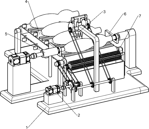
[0041] A wooden handle pressing anti-skid device, such as figure 1 As shown, it includes a base 1, a driving motor 2, an anti-skid printing mechanism 3, an intermittent transport mechanism 4 and a shaft moving mechanism 5. The driving motor 2 is installed on the left front side of the base 1, and the anti-skid printing The anti-slip pattern printing mechanism 3 is connected with the driving motor 2, the middle part of the base 1 is provided with an intermittent transport mechanism 4, the intermittent transport mechanism 4 is connected with the anti-slip pattern printing mechanism 3, and the left and right sides of the front of the base 1 are installed with Shaft moving mechanism 5.

[0042]Place the wooden handle on the parts of the intermittent transport mechanism 4, then start the parts in the drive motor 2 and the rotating shaft moving mechanism 5, the output shaft of the drive motor 2 drives the parts in the anti-slip pattern printing mechanism 3 to rotate, when the anti-s...

Embodiment 2

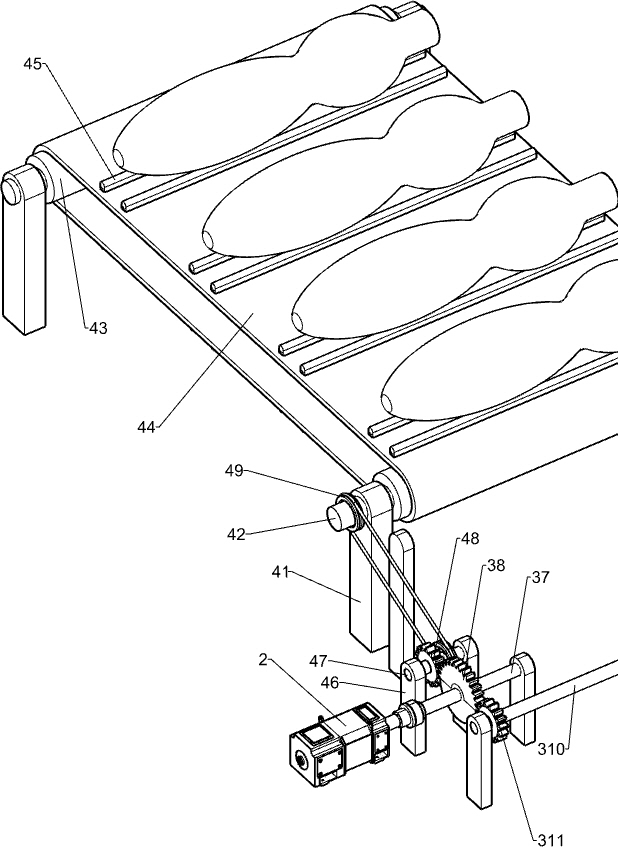
[0044] Specifically, such as Figure 1-3 As shown, the anti-slip pattern printing mechanism 3 includes a first bracket 31, a sliding sleeve 32, a T-shaped connecting rod 33, a roller 34, a pattern cutter 35, a cam 36, a first rotating shaft 37, a half-tooth bull gear 38, a second Support 39, second rotating rod 310, first full-toothed pinion 311 and first belt assembly 312, base 1 middle part front side is provided with first support 31, first support 31 upper rear side is equipped with sliding sleeve 32, sliding sleeve T-shaped connecting rod 33 is connected in sliding type in 32, and is connected by elastic member between sliding sleeve 32 and T-shaped connecting rod 33, and T-shaped connecting rod 33 bottom left and right sides are all provided with roller 34, and T-shaped connecting rod 33 bottoms middle Printing cutter 35 is installed, the left and right sides of the lower part of sliding sleeve 32 are provided with cam 36 through round bar rotation, and cam 36 is in cont...

Embodiment 3

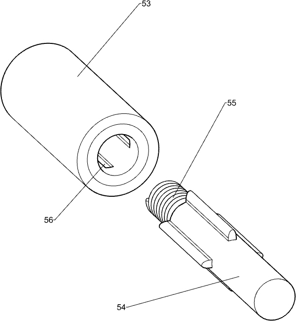
[0049] In particular, refer to figure 1 with Figure 4-6 As shown, the rotating shaft moving mechanism 5 includes a fifth support frame 51, a high-speed motor 52, a rotating cylinder 53, a cross-shaped rotating shaft 54 ​​and a spring 55. The fifth support frame 51 is installed on the right front side of the base 1, and a high Rotating speed motor 52, on the output shaft of high rotating speed motor 52 and on the left side of the top of the fifth support frame 51, rotating drum 53 is equipped with rotating drum 53 and the fifth supporting frame 51, and rotating drum 53 inwall is provided with four A chute 56, slidingly provided with a cross-shaped rotating shaft 54 ​​in the chute 56, the cross-shaped rotating shaft 54 ​​is located directly above the third rotating shaft 42 on the front side, and a spring 55 is connected between the cross-shaped rotating shaft 54 ​​and the rotating cylinder 53.

[0050] Put the wooden handle on the anti-skid bar 45, start the drive motor 2 and...


PUM


Abstract

The invention relates to antiskid stripe devices, in particular to a wooden handle antiskid stripe pressing device which has the technical effects of being capable of automatically pressing antiskid stripes at a time, automatically replacing a wooden handle and automatically cleaning wooden dust. According to the technical scheme, the wooden handle antiskid stripe pressing device comprises a baseand an intermittent conveying mechanism, wherein a driving motor is arranged on the front side of the base; an antiskid stripe printing mechanism is mounted on the front side of the base and connectedwith the driving motor; the intermittent conveying mechanism is arranged in the middle of the base; and a rotary shaft moving mechanism capable of fixing and rotating the wooden handle is arranged between the left and right sides of the front portion of the base. The wooden handle antiskid stripe pressing device can drive a stripe printing cutter to move up and down through the antiskid stripe printing mechanism, can realize antiskid stripe pressing automation of the wooden handle and can intermittently drive the wooden handle to move to the location under the stripe printing cutter through the intermittent conveying mechanism with no need to replace the wooden handle.

Description

technical field [0001] The invention relates to an anti-slip device, in particular to a wooden handle pressing anti-slip device. Background technique [0002] In daily life, we often see some beautiful wooden handles on the handrails of some stairs or wooden furniture. In order to maximize the friction of wooden handles in contact with the human body, the handle manufacturers ensure that people To be able to hold the handle accurately, usually the anti-slip pattern will be pressed on the wooden handle. When pressing the anti-slip pattern, the worker needs to fix the finished handle on the turning machine, and the turning machine will drive the wooden handle to rotate. The anti-slip pattern is created as the knife touches the rotating wooden handle. [0003] This method of artificially pressing the anti-slip pattern on the wooden handle has the disadvantages that the worker needs to touch the handle with a carving knife many times, the wooden handle needs to be replaced manu...

Claims


Application Information

Patent Timeline
IPC IPC(8): B27M1/02B27M3/18
CPCB27M1/02B27M3/18
Inventor 罗文发
Owner 罗文发
Why Eureka
Try Eureka