

Reinforcement sleeve grouting connecting process suitable for fabricated building
A steel sleeve and grouting connection technology, which is applied in the processing of building materials, construction, building components, etc., can solve the problems of operational difficulty, component cost increase, sleeve cost increase, etc., to reduce production difficulty, save cost, reduce cost effect
- Summary
- Abstract
- Description
- Claims
- Application Information
AI Technical Summary
Problems solved by technology
Method used
Image

Examples
Embodiment
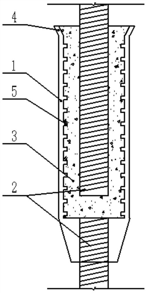
[0035] A steel sleeve grouting connection process suitable for prefabricated buildings, the steps of which are:
[0036] (1) Prefabricated shear wall, the prefabricated shear wall component sleeve 1 is embedded in the upper part of the component, and the steel bar 2 is reserved in the lower part of the component;
[0037] (2) Pouring floor concrete, the height of sleeve 1 is 10-20mm after pouring, mark the elevation on sleeve 1, which is conducive to the control of the thickness of the floor concrete, set out, measure the elevation, and place it well Adjust the pads for the height of the wall, and install the positioning support plate of the wall;
[0038] (3) Remove the plastic cover temporarily blocked by the sleeve 1 on the pouring floor concrete, and inject a sufficient amount of grouting material 3 into the sleeve 1;
[0039] (4) After the prefabricated shear wall is hoisted in place, it is lowered slowly along the positioning support plate. The lower steel bar 2 is inse...
PUM
 Abstract
Description
Claims
Application Information