Automatic switching circuit for hot-redundancy-to-cold-redundancy standby power supply

A redundant backup and automatic power supply technology, applied in the electronic field, can solve problems such as inability to handle heat dissipation of devices, expensive chips, and affecting power conversion efficiency

Pending Publication Date: 2020-09-08
桂林海威科技股份有限公司
View PDF0 Cites 6 Cited by
  • Summary
  • Abstract
  • Description
  • Claims
  • Application Information

AI Technical Summary

Problems solved by technology

The circuit using Schottky diodes has limitations on the current of the output circuit, which will cause the heat dissipation of the device under high current conditions to be unable to handle, thus affecting the conversion efficiency of the power supply
The circuit using a dedicated chip, the chip is expensive, and the dedicated chip requires many peripheral circuits

Method used


Image

  • Automatic switching circuit for hot-redundancy-to-cold-redundancy standby power supply
  • Automatic switching circuit for hot-redundancy-to-cold-redundancy standby power supply
  • Automatic switching circuit for hot-redundancy-to-cold-redundancy standby power supply

Examples


Embodiment

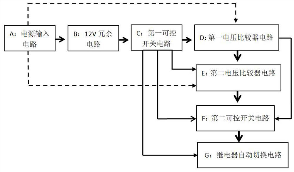
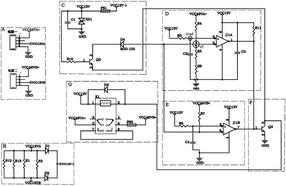
[0039] refer to figure 1 , figure 2 ,

[0040] An automatic switching circuit for hot redundant to cold redundant backup power supply, comprising sequentially connected power supply input circuit A, 12V redundant circuit B, first controllable switch circuit C, first voltage comparator circuit D, second voltage comparator circuit circuit E, the second controllable switch circuit F and relay automatic switching circuit G, wherein, the power input circuit A is also connected with the first voltage comparator circuit D and the second voltage comparator circuit E; the first controllable switch circuit C It is also connected with the second voltage comparator circuit E, the second controllable switch circuit F and the relay automatic switching circuit G; the first voltage comparator circuit D is also connected with the second controllable switch circuit F.

[0041] The power input circuit A includes a first power supply and a second power supply with the same structure connected ...


PUM


Abstract

The invention discloses an automatic switching circuit for a hot-redundancy-to-cold-redundancy standby power supply. The automatic switching circuit comprises a power supply input circuit A, a 12V redundant circuit B, a first controllable switch circuit C, a first voltage comparator circuit D, a second voltage comparator circuit E, a second controllable switch circuit F and a relay automatic switching circuit G which are connected in sequence, wherein the power supply input circuit A is also connected with the first voltage comparator circuit D and the second voltage comparator circuit E, thefirst controllable switch circuit C is also connected with the second voltage comparator circuit E, the second controllable switch circuit F and the relay automatic switching circuit G, and the firstvoltage comparator circuit D is also connected with the second controllable switch circuit F. According to the invention, the circuit can realize cold standby of two paths of power supply output, accelerates the power supply switching speed, is low in circuit cost, and can effectively avoid the problem of mutual interference between two power supplies when the power supply module is applied to work in a hot redundancy state.

Description

technical field [0001] The invention relates to the field of electronic technology, in particular to an automatic switching circuit for hot redundant to cold redundant backup power supply. Background technique [0002] With the continuous development of electronic circuits, electronic products are becoming more and more intelligent. In order to ensure the reliable operation of products, the power supply of important circuits inside these electronic products generally uses dual power supply redundant power supply. When one power supply has no output, it can seamlessly switch to another power supply; or when one output is abnormal, it can seamlessly switch to another power supply. [0003] At present, when designing the internal circuit of electronic products, Schottky diodes or dedicated chips are generally used in the dual power supply circuit to realize parallel connection of output power. The circuit using the Schottky diode has limitations on the current of the output ci...

Claims


Application Information

Patent Timeline
Patent Type & Authority Applications(China)
IPC IPC(8): H02J9/00H02J9/06
CPCH02J9/00H02J9/06Y02B70/30Y04S20/20
Inventor 蒋恒汤谷心丁倩覃沿日李飞云
Owner 桂林海威科技股份有限公司
Why Eureka
Try Eureka