Method and system for reducing motion artifact in pulse wave signal

A motion artifact, pulse wave technology, applied in the measurement of pulse rate/heart rate, medical science, sensors, etc., to reduce motion artifacts, reduce motion artifact signals, and respond consistently

Pending Publication Date: 2020-09-11
上海铼锶信息技术有限公司
View PDF8 Cites 2 Cited by
  • Summary
  • Abstract
  • Description
  • Claims
  • Application Information

AI Technical Summary

Problems solved by technology

Based on the frequency domain direction and the reference signal, remove the motion artifact signal in the pulse wave signal, obtain the heart rate signal, avoid the problem of inconsistency between the pulse wave signal data and the reference signal data in the local motion interference response, and focus on the capture of the heart rate signal, thereby Solve the capture of heart rate signals under large movements

Method used


Image

  • Method and system for reducing motion artifact in pulse wave signal
  • Method and system for reducing motion artifact in pulse wave signal
  • Method and system for reducing motion artifact in pulse wave signal

Examples


Embodiment Construction

[0019] The present invention will be described in detail below in conjunction with specific embodiments shown in the accompanying drawings. In the drawings, components with the same structure are denoted by the same numerals, and components with similar structures or functions are denoted by similar numerals. The size and thickness of each component shown in the drawings are shown arbitrarily, and the present invention does not limit the size and thickness of each component. In order to make the illustration clearer, the thickness of parts is appropriately exaggerated in some places in the drawings.

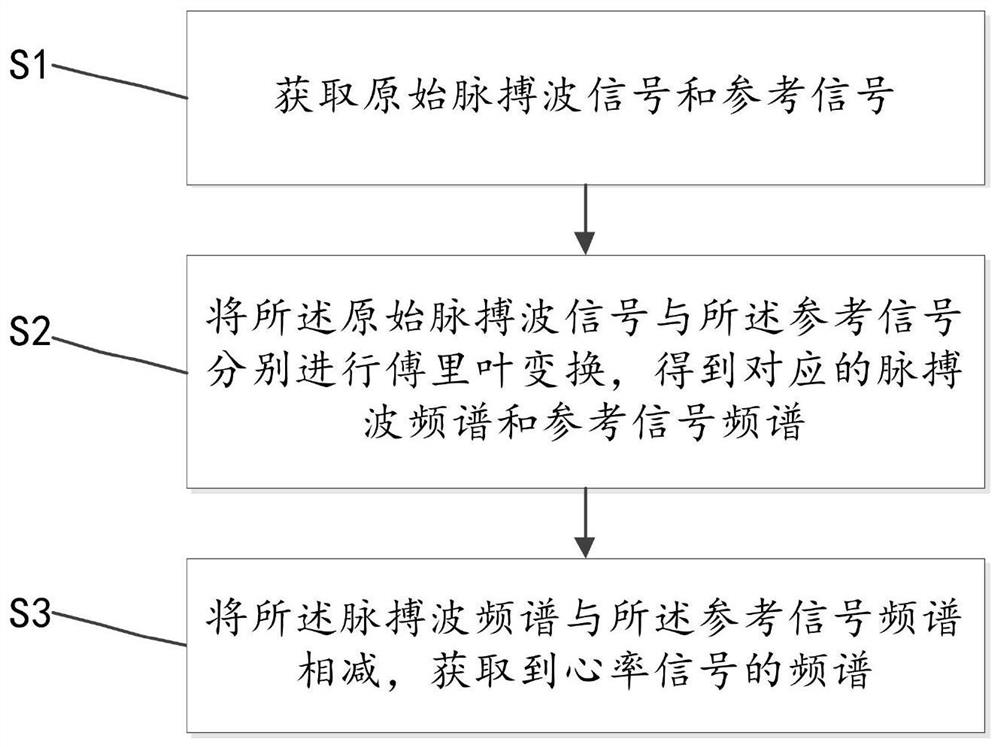
[0020] Such as figure 1 As shown, a method for reducing motion artifacts in a pulse wave signal according to an embodiment of the present invention includes:

[0021] S1. Obtain the original pulse wave signal and the reference signal;

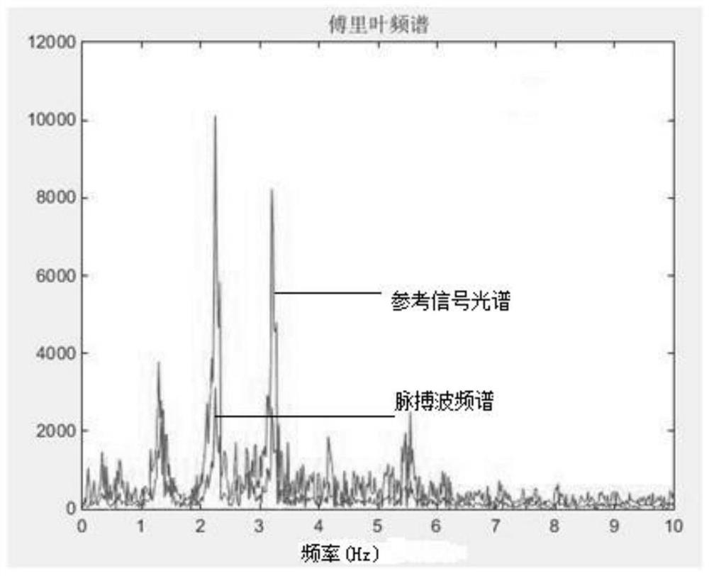
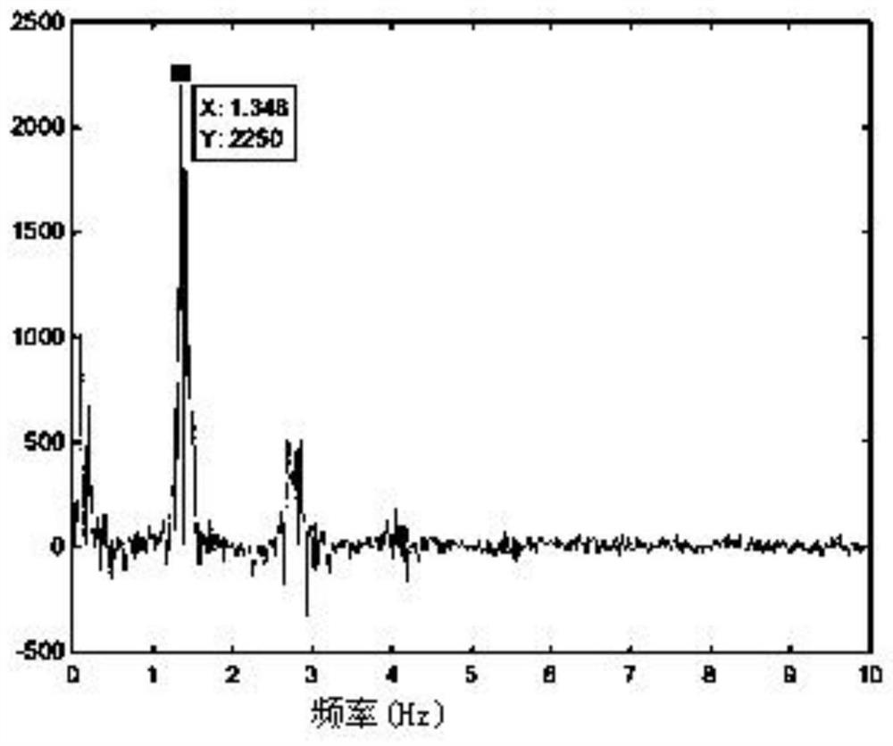
[0022] S2. Perform Fourier transform on the original pulse wave signal and the reference signal respectively to obtain corresponding pulse wav...


PUM


Abstract

The invention relates to the technical field of digital signal processing and discloses a method for reducing a motion artifact in a pulse wave signal. The method comprises the steps of acquiring an original pulse wave signal and a reference signal; carrying out Fourier transformation on the original pulse wave signal and the reference signal separately to obtain corresponding pulse wave spectrumand reference signal spectrum; and subtracting the pulse wave spectrum from the reference signal spectrum to obtain a spectrum of a heart rate signal. The invention further correspondingly discloses asystem for reducing the motion artifact in the pulse wave signal. According to the method and the system, the motion artifact in the pulse wave signal can be effectively reduced and capture of the heart rate signal under strong motion is achieved.

Description

technical field [0001] The invention relates to the technical field of digital signal processing, in particular to a method and system for reducing motion artifacts in pulse wave signals. Background technique [0002] Photoplethysmography technology uses photoelectric sensors to detect the difference in the intensity of reflected light absorbed by human blood and tissues, traces the changes in blood vessel volume during the cardiac cycle, and calculates the heart rate from the obtained pulse wave waveform. The more common use of smart wearable devices can detect pulse wave signals in real time, and then obtain heart rate information. However, there is a contact gap between the pulse wave acquisition device and the skin, which causes the measurement optical path to change during the movement, resulting in the waveform of the pulse wave being superimposed with motion interference noise, which has a great impact on the calculation of physiological feature information using the ...

Claims


Application Information

Patent Timeline
Patent Type & Authority Applications(China)
IPC IPC(8): A61B5/00A61B5/024
CPCA61B5/02416A61B5/7207
Inventor 杨旗龙
Owner 上海铼锶信息技术有限公司
Why Eureka
Try Eureka