MR shimming auxiliary device
A field assist and headrest technology is applied in the field of MR shimming assist devices to achieve the effects of ensuring comfort, improving fat suppression effect, and high device comfort
- Summary
- Abstract
- Description
- Claims
- Application Information
AI Technical Summary
Problems solved by technology
Method used
Image

Examples
specific Embodiment approach 1
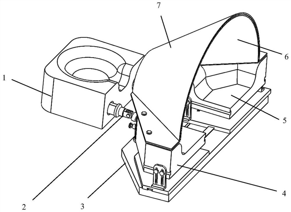
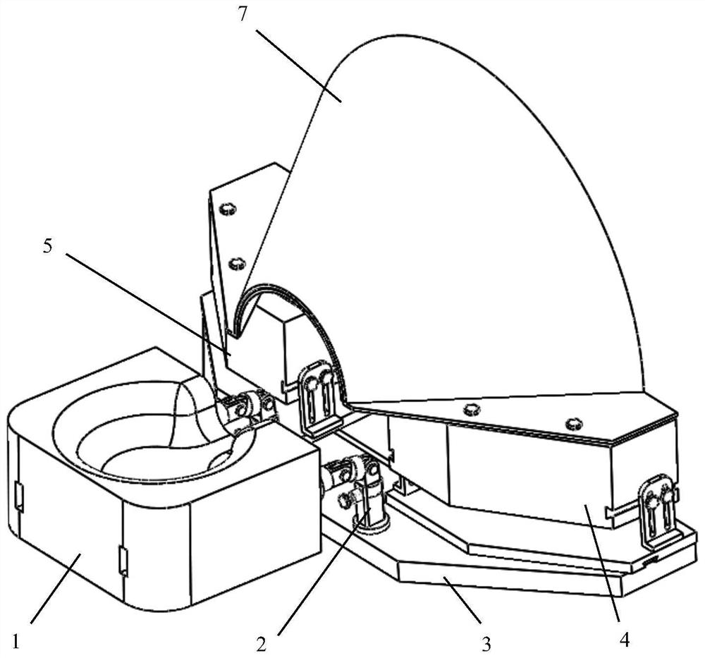
[0064] An MR shimming auxiliary device in this embodiment, such as figure 1 , 2 As shown, its composition includes headrest mechanism 1, headrest adjustment mechanism 2, liner mechanism 3, left shoulder rest mechanism 4, right shoulder rest mechanism 5, silicone pad 6, thermoplastic diaphragm 7;
[0065] The liner mechanism 3 is a sheet-layer plate, and the liner mechanism 3 is used as the supporting part of the MR shimming auxiliary device. The left and right shoulder rest mechanisms 4 and 5 are respectively installed on the left and right sides of the upper end surface of the liner mechanism 3, and the left shoulder rest mechanism 4 and the right shoulder support mechanism 5 are arranged to slide left and right on the upper end surface of the liner mechanism 3; the headrest adjustment mechanism 2 is installed on the front part of the upper end surface of the liner mechanism 3, and the headrest adjustment mechanism 1 is installed at the end of the headrest adjustment mechanis...
specific Embodiment approach 2
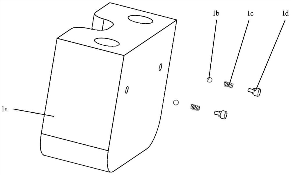
[0068] The difference from Embodiment 1 is that an MR shimming auxiliary device in this embodiment, such as Figure 3-6 As shown, the headrest mechanism 1 includes a headrest 1a, 4 headrest steel balls 1b, 4 headrest springs 1c, and 4 headrest locking and fixing seats 1d;
[0069] A headrest pit 1a1 is provided at the upper middle position of the headrest 1a;
[0070] In the longitudinal direction inside the main body of the headrest 1a, two adjustment guide grooves 1a2 are symmetrically arranged on the left and right sides, and the upper and lower ends of each adjustment guide groove 1a2 are symmetrically provided with locking grooves 1a3, and the side walls of the locking grooves 1a3 are provided with threads ;
[0071] In each locking groove 1a3, the headrest spring 1c is set on the front end of the headrest lock fixing seat 1d, and the headrest steel ball 1b is connected to the front end of the headrest spring 1c; the headrest steel ball 1b, the headrest spring 1c, the he...
specific Embodiment approach 3
[0075] The difference from Embodiment 1 or Embodiment 2 is that an MR shimming auxiliary device in this embodiment, such as Figure 7-11 As shown, the left shoulder rest mechanism 4 includes a left shoulder rest base plate 4a, two shoulder rest brackets 4b, a set of handle bolts 4c, a left shoulder rest 4d, a thermoplastic connection block 4e, and a set of shoulder rest wedges 4f;
[0076] The left shoulder support base plate 4a is a sheet structure, located at the bottom of the left shoulder support mechanism 4, and the bottom of the left shoulder support base plate 4a is slidably connected with the lining plate mechanism 3;
[0077] The bottom of each shoulder support bracket 4b is installed on the left shoulder support base plate 4a, and a group of elongated hole structures are provided on the shoulder support support 4b; the top of the shoulder support support 4b is connected to the left shoulder support 4d;
[0078] The longitudinal section of the left shoulder rest 4d is...
PUM
 Abstract
Description
Claims
Application Information
 - R&D
- Intellectual Property
- Life Sciences
- Materials
- Tech Scout
- Unparalleled Data Quality
- Higher Quality Content
- 60% Fewer Hallucinations
Browse by: Latest US Patents, China's latest patents, Technical Efficacy Thesaurus, Application Domain, Technology Topic, Popular Technical Reports.
© 2025 PatSnap. All rights reserved.Legal|Privacy policy|Modern Slavery Act Transparency Statement|Sitemap|About US| Contact US: help@patsnap.com