
An environmentally friendly spray booth

A paint spray booth, environmentally friendly technology, applied in the direction of spray devices, etc., can solve the problem of reducing the air flow area, and achieve the effect of reducing the flow area and increasing the friction force.

Active Publication Date: 2021-06-11
蔡欧
View PDF7 Cites 0 Cited by
  • Summary
  • Abstract
  • Description
  • Claims
  • Application Information

AI Technical Summary

Problems solved by technology

[0003] Based on the inventors' discovery above, the existing environment-friendly spray booth mainly has the following disadvantages, such as: due to the strong adhesion with the paint powder, in the process of spraying the car, there will be some The paint powder floats into the air of the spray booth, and is sucked into the ventilation pipe by the airflow generated by the rotation of the exhaust fan, so that the paint powder adheres to the filter in the ventilation opening, reducing the flow area of ​​the airflow

Method used


Image

  • An environmentally friendly spray booth
  • An environmentally friendly spray booth
  • An environmentally friendly spray booth

Examples


Embodiment 1

[0026] Example 1: Please refer to Figure 1-Figure 5 , the specific embodiments of the present invention are as follows:

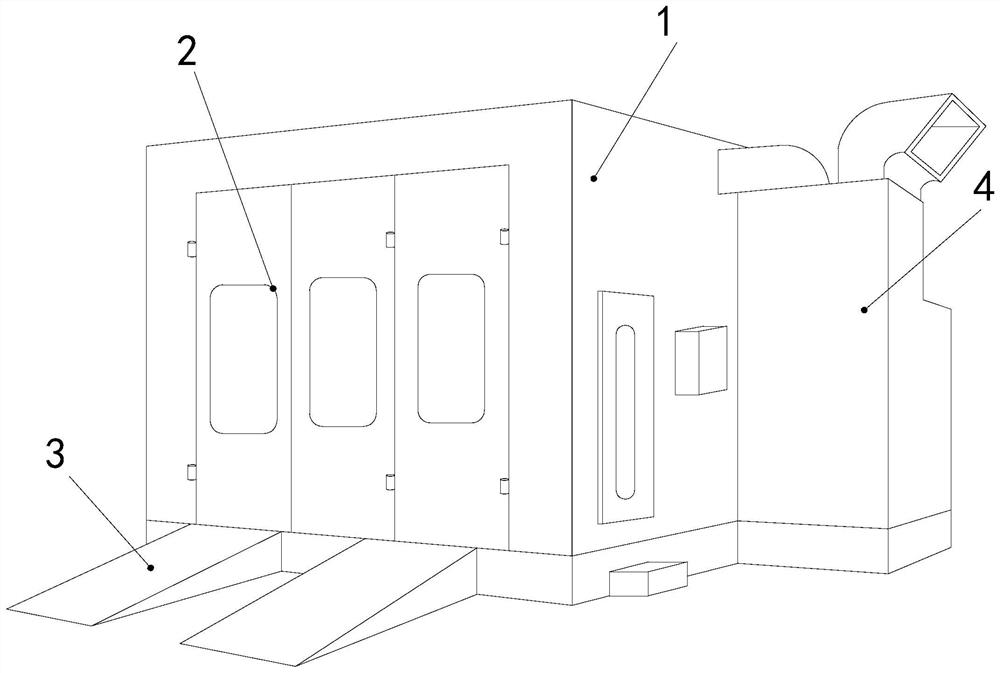
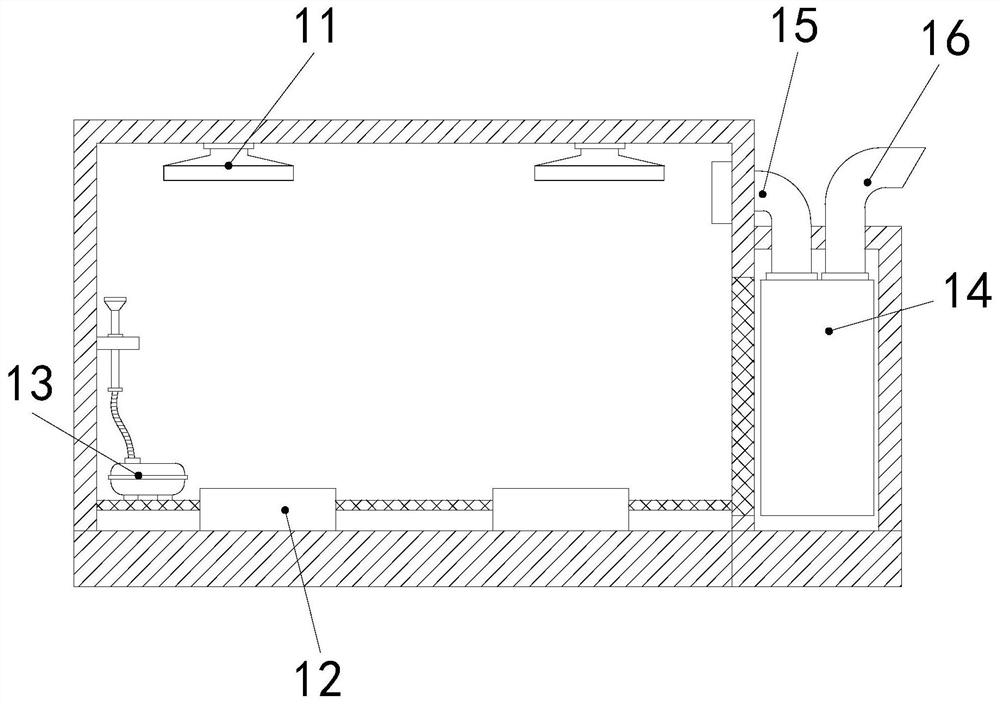
[0027] Its structure includes a room body 1, a door 2, a support frame 3, and an air purification block 4. The front end of the room body 1 is provided with a door 2, and there are two support frames 3 arranged horizontally on the door 2. The front end of the air purification block 4 is installed at the side end of the room body 1, and the room body 1 includes an illumination lamp 11, a support block 12, a dust suction block 13, a purification block 14, an air suction pipe 15, and an exhaust pipe 16. There are two illuminating lamps 11 installed on the top of the room body 1, two supporting blocks 12 are installed at both ends of the bottom of the room body 1, and the dust suction block 13 is arranged on the top of the room body. The inner side end of the body 1, the purification block 14 is embedded in the side end of the room body 1, one end of the exha...

Embodiment 2

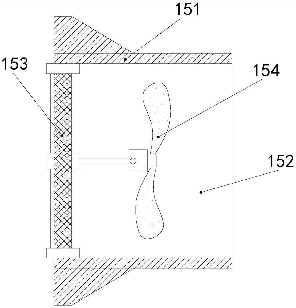
[0032] Example 2: Please refer to Figure 6-Figure 8 The specific embodiment of the present invention is as follows: the scraping block a3 includes a rotating shaft a31, a scraping body a32, a connecting rod a33, and a connecting block a34, and eight scraping bodies a32 are arranged at the side end of the rotating shaft a31, and four It is a group embedded in the side end of the rotating shaft a31, the connecting rod a33 is embedded in the rear end of the rotating shaft a31, the connecting block a34 is embedded in the rear end of the connecting rod a33, and is connected with the fan 154. The distance between the two sets of scraping bodies a32 at the side end of the rotating shaft a31 and the horizontal plane is greater than the width between the filter screens a2, which is beneficial for the scraping body a32 to rotate through the rotating shaft a31 and scrape off the paint powder attached to the filter screen a2 .

[0033] The scraping body a32 includes a base b1, a fixing ...


PUM


Abstract

The invention discloses an environment-friendly paint spraying room. The structure includes a room body, a door, a support frame and an air purification block. The front end of the room body is provided with a door, and two support frames are arranged horizontally at the front end of the door. , the air purification block is installed at the side end of the room body, the room body includes the irradiation lamp, the support block, the vacuum block, the purification block, the exhaust pipe, the exhaust pipe, the exhaust pipe includes the fixed port, the ventilation hole, the filter block, the fan, the filter The block includes an outer ring body, a filter screen, and a scraping block. The outer ring body includes a dust collecting groove, an entry groove, a fixing block, and a cleaning door. Rotate, so that the scraping block connected with the fan scrapes off the paint powder attached to the surface of the filter screen, avoiding the paint powder sticking to the filter screen, reducing the flow area of ​​the airflow, and affecting the purification of the air in the room.

Description

technical field [0001] The invention relates to the field of environmental protection, in particular to an environment-friendly spray booth. Background technique [0002] The spray booth is a kind of spraying and grinding processing equipment, which is used to provide a working environment isolated from the outside world, which can not only ensure the processing quality, but also avoid the pollution of the environment by the paint mist and smoke generated by the processing; the spray booth can meet the temperature requirements of the coating operation. , humidity, illuminance, air cleanliness and other requirements, it is an environmentally friendly coating equipment, the spray booth is mainly used to paint the car shell, because the car shell is mainly sprayed with powder paint. [0003] Based on the inventors' discovery above, the existing environment-friendly spray booth mainly has the following disadvantages, such as: due to the strong adhesion with the paint powder, in ...

Claims


Application Information

Patent Timeline
Patent Type & Authority Patents(China)
IPC IPC(8): B05B15/50
CPCB05B15/50
Inventor 潘展成
Owner 蔡欧
Learn More