Steel bar bundling structure and bundling method

A technology of steel bar and opening structure, which is applied to the parts and packaging of bundling machinery, can solve the problems of unsuitable steel bars, roughness, and difficulty in realizing the accumulation of steel bars, so as to achieve the effect of convenient bundling.

Active Publication Date: 2020-09-11
中铁十四局集团建筑工程有限公司
View PDF4 Cites 0 Cited by
  • Summary
  • Abstract
  • Description
  • Claims
  • Application Information

AI Technical Summary

Problems solved by technology

[0005] There are cable transportation and bundling equipment on the market now, which use smooth docking brackets and regular brackets to regularize the cables, and then use the binding strips on the outside of the regular brackets for bundling, which can effectively save manpower, but this structure is not suitable for steel bars. Since the surface of the steel bar is rough compared to the cable, it is difficult to achieve the accumulation of the steel bar

Method used


Image

  • Steel bar bundling structure and bundling method
  • Steel bar bundling structure and bundling method
  • Steel bar bundling structure and bundling method

Examples


Embodiment 1

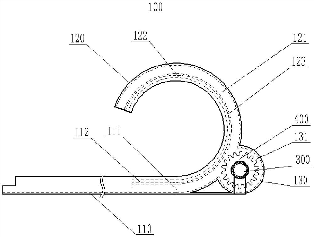
[0029] Such as figure 1 , 2 As shown, a steel bar binding structure includes a frame body 100, a driving strip 200, a binding assembly and a driving assembly; 120 connection, the upper surface of the docking bracket 110 is a smooth surface, and the regular bracket 120 is an arc-shaped structure; the docking bracket 110 and the regular bracket 120 are provided with accommodating chambers connected to each other, and the driving strip 200 can be movably installed In the accommodating cavity, the driving bracket 130 is provided with a driving cavity 131, the driving cavity 131 communicates with the accommodating cavity, the driving assembly is installed on the driving bracket 130, and the driving assembly drives the strip 200 in the accommodating cavity move; the upper surface of the docking support 110 near the end of the regular support 120 is an open structure, the contact surface between the regular support 120 and the steel bar is an open structure, and the driving strip 20...

Embodiment 2

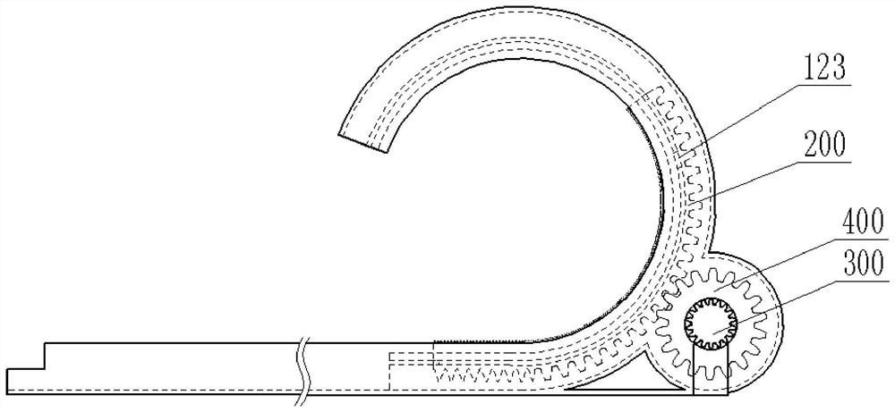
[0035] Such as figure 1 , 2As shown, the accommodating cavity of the docking bracket 110 is a closed structure at one end away from the regular bracket 120, thereby facilitating the limitation of the starting position of the driving strip 200, and the accommodating cavity of the docking bracket 120 is open at one end away from the docking bracket 110. Structure, when in use, the driving strip 200 can extend out of the regular support 120, and when it extends to a certain extent, it can limit the height of the steel bars that are subsequently transported to the end of the docking support 110, or can help to regularize the steel bars that have already been located in the regular support 120, which is convenient for follow-up Bundle actions using bundle components.

Embodiment 3

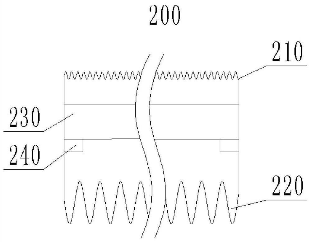
[0037] In order to ensure that the driving strip 200 has enough space for movement, preferably, the length of the driving strip 200 is smaller than the length of the accommodation cavity. In order to avoid protruding out of the regular support 120 once the driving bar 200 moves, affecting subsequent use.

[0038] In the steel bar binding structure and binding method provided by the present invention, the drive assembly drives the belt bar 200 to generate displacement, so that the steel bars accumulated or gathered at the starting end of the belt bar 200 move to the root of the regular support 120, so that the aggregated shape of the steel bars tends to be arc-shaped and because the upper surface of the docking support 110 is a smooth surface, after the driving bar 200 shifts, the reinforcing bar will continue to move towards the root of the regular support 120 under the thrust of the follow-up reinforcing bar, thereby facilitating the use of a binding structure to bind the rein...


PUM


Abstract

The invention provides a steel bar bundling structure and bundling method, and relates to the field of building construction. A butt joint support and an arranging support of the steel bar bundling structure are connected, accommodating cavities communicating with each other are arranged in the butt joint support and the arranging support, a driving strip is movably arranged in each accommodatingcavity, and a driving assembly drives the driving strips to move in the accommodating cavities; and each of the upper surface of the end, close to the arranging support, of the butt joint support andthe surface, making contact with a steel bar, of the arranging support is provided with an opening structure, the upper surface of the butt joint support is a smooth surface, and the arranging supportis of an arc-shaped structure. When the steel bars are bundled, the steel bars are conveyed to the steel bar bundling structure through a conveying device, when the steel bars make contact with the surfaces of the driving strips, stacking of the steel bars is gradually started, the driving assembly drives the driving strips to move, the driving strips drive the steel bars to move towards the roots of the arranging support, then the steel bars are bundled by using a bundling assembly, and then the driving strips are reversely driven to return to the initial positions after bundling is completed. Using the scheme can facilitate conveying of a large quantity of steel bars.

Description

technical field [0001] The invention belongs to the field of building construction, and in particular relates to a steel bar binding structure and a binding method. Background technique [0002] In the construction industry, steel bars are an indispensable material, and in the construction of new buildings or the manufacture of prefabricated components, the laying of steel bars is also essential, and large quantities of steel bars are usually required. [0003] However, due to the large number and heavy weight of steel bars in bulk transportation, it is easy to cause loose steel bars or excessively tight binding, which will damage the anti-corrosion layer of steel bars (if any), which is not convenient for the transportation of steel bars. [0004] Therefore be badly in need of providing a kind of equipment that can carry out effective protection or binding to the transportation of large quantities of steel bars. [0005] There are cable transportation and bundling equipmen...

Claims


Application Information

Patent Timeline
IPC IPC(8): B65B13/20B65B27/10
CPCB65B13/20B65B27/10
Inventor 冯国森李占先代显奇王孝波王伟伟李延吕世华孟祥林刘强
Owner 中铁十四局集团建筑工程有限公司
Why Eureka
Try Eureka