
Valve guide pipe drilling, loading and conveying apparatus

A valve guide and conveying device technology, which is applied to conveyer objects, transportation and packaging, etc., can solve problems such as affecting operation efficiency and disorderly arrangement of valve guides, and achieve the effect of convenient drilling

Pending Publication Date: 2020-09-11
辉门环新(安庆)粉末冶金有限公司
View PDF1 Cites 1 Cited by
  • Summary
  • Abstract
  • Description
  • Claims
  • Application Information

AI Technical Summary

Problems solved by technology

[0003] The technical problem to be solved by the present invention is that the existing valve guide feeding device easily causes the arrangement of the valve guides to be disordered during the conveying process, and the conveyed valve guides need to be rearranged to form a row, which affects the operating efficiency

Method used


Image

  • Valve guide pipe drilling, loading and conveying apparatus
  • Valve guide pipe drilling, loading and conveying apparatus
  • Valve guide pipe drilling, loading and conveying apparatus

Examples


Embodiment Construction

[0031] In order to make the purpose, technical solutions and advantages of the embodiments of the present invention clearer, the technical solutions in the embodiments of the present invention will be clearly and completely described below in conjunction with the embodiments of the present invention. Obviously, the described embodiments are part of the present invention Examples, not all examples. Based on the embodiments of the present invention, all other embodiments obtained by persons of ordinary skill in the art without creative efforts fall within the protection scope of the present invention.

[0032] It should be noted that when an element is referred to as being “fixed” to another element, it can be directly on the other element or there can also be an intervening element. When an element is referred to as being "connected to" another element, it can be directly connected to the other element or intervening elements may also be present.

[0033] It should be noted th...


PUM


Abstract

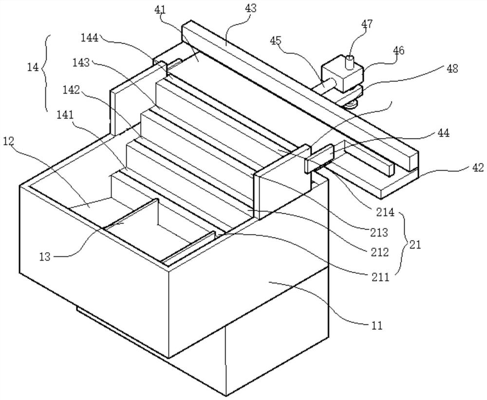
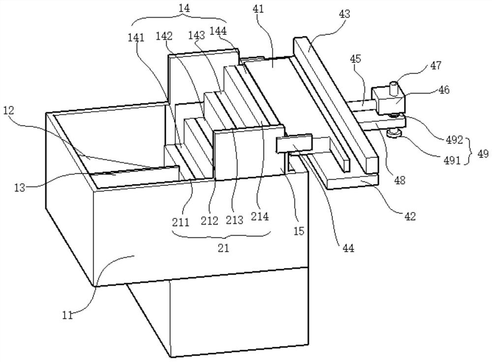
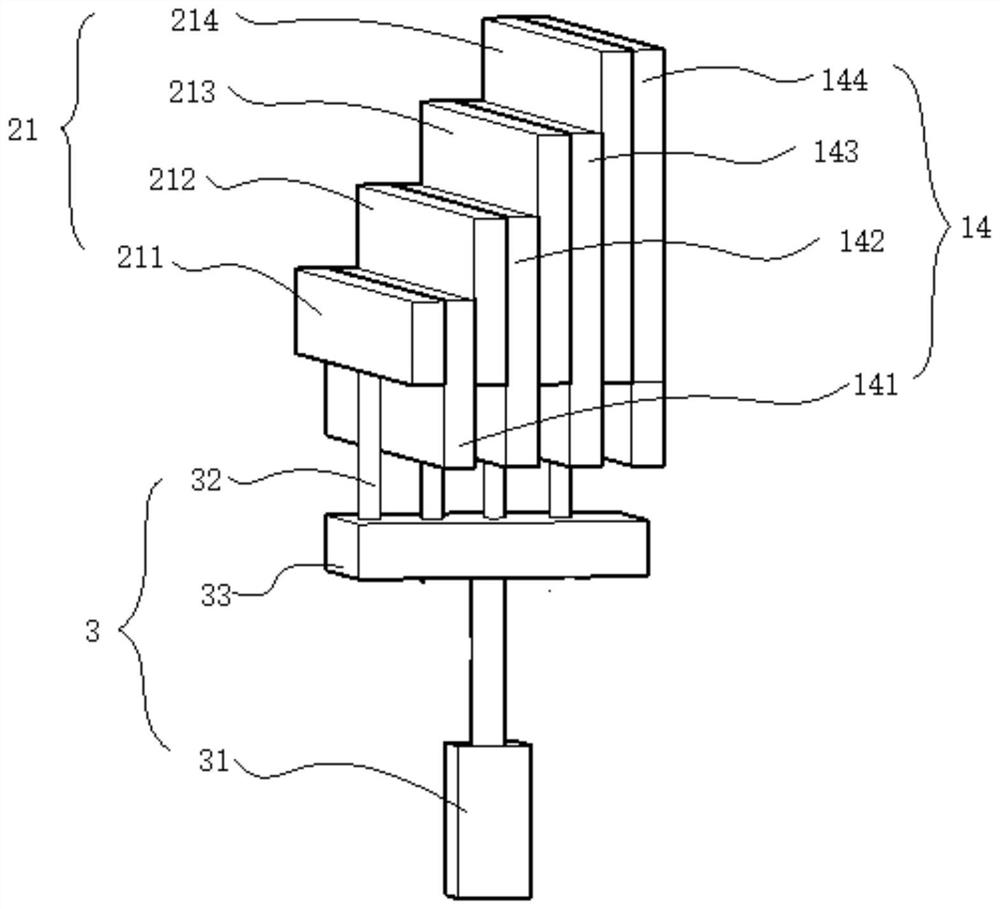
The present invention discloses a valve guide pipe drilling, loading and conveying apparatus, relating to the technical field of valve guide pipes. The apparatus of the present invention comprises a workbin, a loading unit and a conveying unit; the loading unit is positioned on one side of the workbin; the conveying unit comprises a conveying plate, a conveying belt and a first baffle plate; the conveying plate is positioned at the top end of a box body; the conveying belt is positioned under the conveying plate; the first baffle plate is positioned on the top wall of the conveying plate; theside wall of the first baffle plate, the side wall of the conveying plate and the conveying belt define a channel for conveying valve guide pipes; and the loading unit moves up and down, so that the valve guide pipes are loaded to the top end of the workbin from the bottom of the workbin in sequence, and then are conveyed onto the conveying belt from the conveying plate. The present invention hasthe beneficial effects that: the valve guide pipe drilling, loading and conveying apparatus can directly convey the valve guide pipes after loading and conveying, and moreover, only allows one valve guide pipe to pass through by adjusting the size of the channel to directly implement ordered conveying so as to conveniently drill the conveyed valve guide pipes.

Description

technical field [0001] The invention relates to the technical field of valve guides, in particular to a valve guide drilling and feeding conveying device. Background technique [0002] The valve guide is the guide device for the valve of the automobile engine. The valve guide guides the valve and transfers the heat on the valve stem to the cylinder head through the valve guide. Before drilling the valve guide, the valve guide needs to be transported to the drilling device. For example, the patent application with publication number CN110170677A discloses a cylinder head valve guide hole processing equipment. The existing valve guide feeding device easily causes the arrangement of the valve guides to be disordered during the conveying process. Rearrange them to form a column, which affects operating efficiency. Contents of the invention [0003] The technical problem to be solved by the present invention is that the existing valve guide feeding device easily causes the arr...

Claims


Application Information

Patent Timeline
Patent Type & Authority Applications(China)
IPC IPC(8): B65G47/14
CPCB65G47/1471
Inventor 张国富汪举陆胡飞
Owner 辉门环新(安庆)粉末冶金有限公司
Learn More