
Cooling wall structure of blast furnace

A stave and blast furnace technology, applied in the direction of cooling devices, etc., can solve the problems of cooling pipes and connecting pipes hindering the flow of cooling water, difficult installation of connecting pipes and valves, and damage to the structural strength of the furnace shell, etc., so as to facilitate pipe penetration maintenance and easy The effect of sealing and preventing high-temperature gas leakage

Pending Publication Date: 2020-09-11
CISDI ENG CO LTD
View PDF0 Cites 1 Cited by
  • Summary
  • Abstract
  • Description
  • Claims
  • Application Information

AI Technical Summary

Problems solved by technology

[0006] In view of this, the object of the present invention is to provide a blast furnace stave structure, the cooling pipes in the stave wall go straight in and out without bending, the water inlets and outlets are no longer centrally arranged, and the openings on the furnace shell Set one-to-one with water inlet and water outlet instead of one-to-many, solve the existing structure where three or more water inlets and water outlets are arranged in one place, and larger openings need to be set on the furnace shell to destroy the furnace The structural strength of the shell and poor sealing are likely to cause high-temperature gas leakage, reducing the service life of the furnace shell, and due to the centralized arrangement, there are many bends in the cooling pipes and connecting pipes that hinder the flow of cooling water, which is not conducive to the later maintenance of pipes, connecting pipes and Valve installation is difficult and time-consuming

Method used


Image

  • Cooling wall structure of blast furnace
  • Cooling wall structure of blast furnace
  • Cooling wall structure of blast furnace

Examples


Embodiment Construction

[0028] The preferred embodiments of the present invention will be described in detail below with reference to the accompanying drawings.

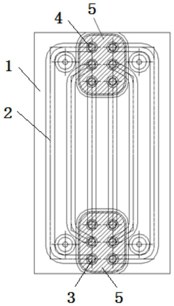
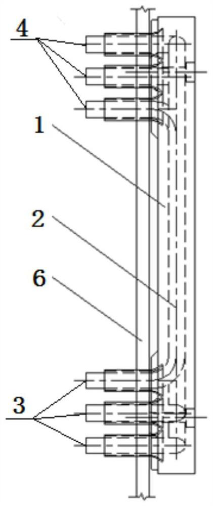
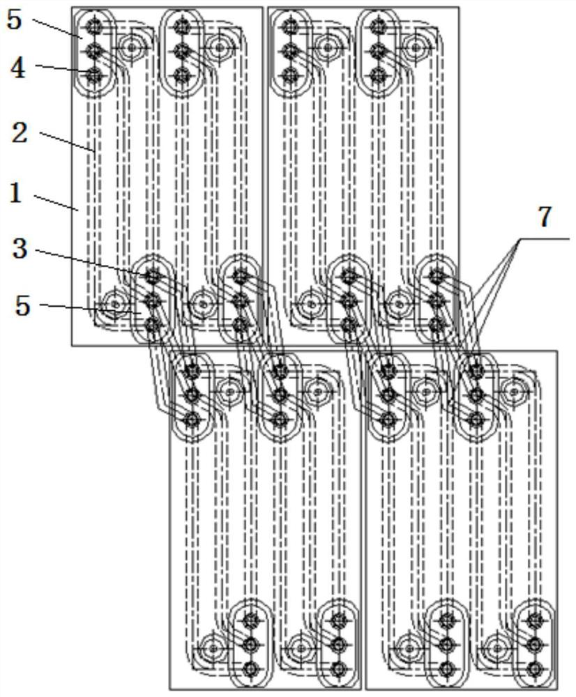
[0029] Such as Figure 5 and Figure 6 As shown, a blast furnace stave structure includes a multi-section stave 1, and six cooling pipes 2 are arranged in the wall body of each section of the stave 1, and the lower end of each section cooling pipe 2 is a water inlet 3, and the upper end is a water outlet 4, The water inlet 3 and the water outlet 4 pass through the furnace shell 6 of the blast furnace located on the outside of the stave 1, and the cooling pipes 2 of the adjacent upper and lower staves 1 are sequentially connected by connecting pipes 7 to form six cooling passages from bottom to top. The six cooling pipes 2 in the wall of each stave 1 are vertically parallel and arranged at equal intervals, the water inlet 3 and the water outlet 4 of the adjacent cooling pipes 2 are respectively arranged at random heights, and the height of ...


PUM


Abstract

The present invention relates to a cooling wall structure of a blast furnace, belonging to the technical field of blast furnace smelting devices. The structure comprises multiple sections of cooling walls; multiple cooling pipes are provided in a wall body of each section of cooling wall; the lower end of each section of cooling pipe is a water inlet, and the upper end is a water outlet; the waterinlet and the water outlet penetrate outside a furnace shell of the blast furnace located on the outer sides of the cooling walls; the cooling pipes on the upper and lower adjacent sections of cooling walls are connected in sequence by means of contact pipes to form multiple cooling channels from bottom to top; multiple cooling pipes in the wall body of each section of cooling wall are verticallyarranged in parallel; the water inlets and the water outlets of the adjacent cooling pipes are staggered high and low, respectively; and open holes are correspondingly provided on the furnace shell and the water inlets and the water outlets staggered on the cooling pipes high and low one to one. The cooling pipes straightly enter and exit to solve the problems of destruction of the structural strength of the furnace shell caused by larger open holes due to one-to-many arrangement of the open holes on an existing furnace shell and the water inlets and the water outlets and difficult mounting of the contact pipes and valves caused by stop of the flowing of cooling water due to more bends of the cooling pipes and the contact pipes.

Description

technical field [0001] The invention belongs to the technical field of blast furnace smelting equipment, and relates to a cooling wall structure of a blast furnace. Background technique [0002] The furnace wall structure of a blast furnace can be roughly divided into refractory materials, staves, fillers and furnace shells from the inside to the outside. The cooling stave is an important cooling equipment for the blast furnace. The cooling stave is generally made of copper, cast iron or cast steel. Cooling pipes are cast into the stave wall, and the steel pipes cast into the stave wall of each upper and lower sections pass through the outer side of the stave. After the shell of the blast furnace, it is connected by connecting pipes to form a bottom-up cooling channel, and high-speed flowing cooling water is introduced into the cooling channel to quickly remove the heat from the cooling wall to maintain the stable production of the blast furnace. [0003] Since the cooling ...

Claims


Application Information

Patent Timeline
Patent Type & Authority Applications(China)
IPC IPC(8): C21B7/10
CPCC21B7/10
Inventor 徐灿屈俊杰李杰游梅英
Owner CISDI ENG CO LTD
Learn More