Al technical title is built by PatSnap Al team. It summarizes the technical point description of the patent document.
A compaction device and fast technology, applied in the field of building foundation, can solve the problems of shortening construction time, accelerating foundation compaction, low technical requirements, etc., to achieve the effect of improving work efficiency and reducing air resistance
Pending Publication Date: 2020-09-11
CHINA THIRD METALLURGICAL GRP
View PDF0 Cites 0 Cited by
Summary
Abstract
Description
Claims
Application Information
AI Technical Summary
This helps you quickly interpret patents by identifying the three key elements:
Problems solved by technology
Method used
Benefits of technology
Problems solved by technology
[0005] The invention provides a rapid compaction device and a construction method. In order to solve a series of technical problems caused by the traditional compaction equipment in the working process, a combination of a compaction plate and a percussion drill is adopted to quickly compact the backfill. On the ground, the tamping device has a simple structure, flexible and convenient operation, and is not prone to mechanical failure. The combination of the tamping device and the excavator can move flexibly, facilitate rapid movement and switch angles, greatly speed up the construction speed of the tamped foundation, and improve the The compaction efficiency shortens the construction time, and this compaction device has lower technical requirements for the operator, which reduces the construction strength of the workers and improves the work efficiency of the workers
Method used
Image
Click on the blue label to locate the original text in one second.
Reading with bidirectional positioning of images and text.
Examples
Embodiment Construction
[0028] The specific embodiment of the present invention will be further described below in conjunction with accompanying drawing:
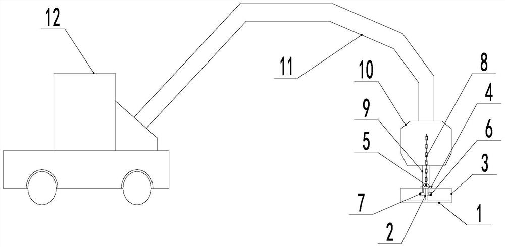
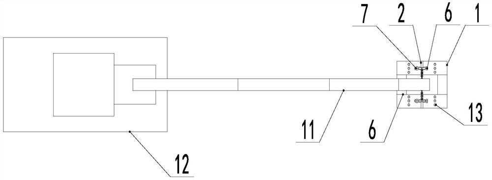
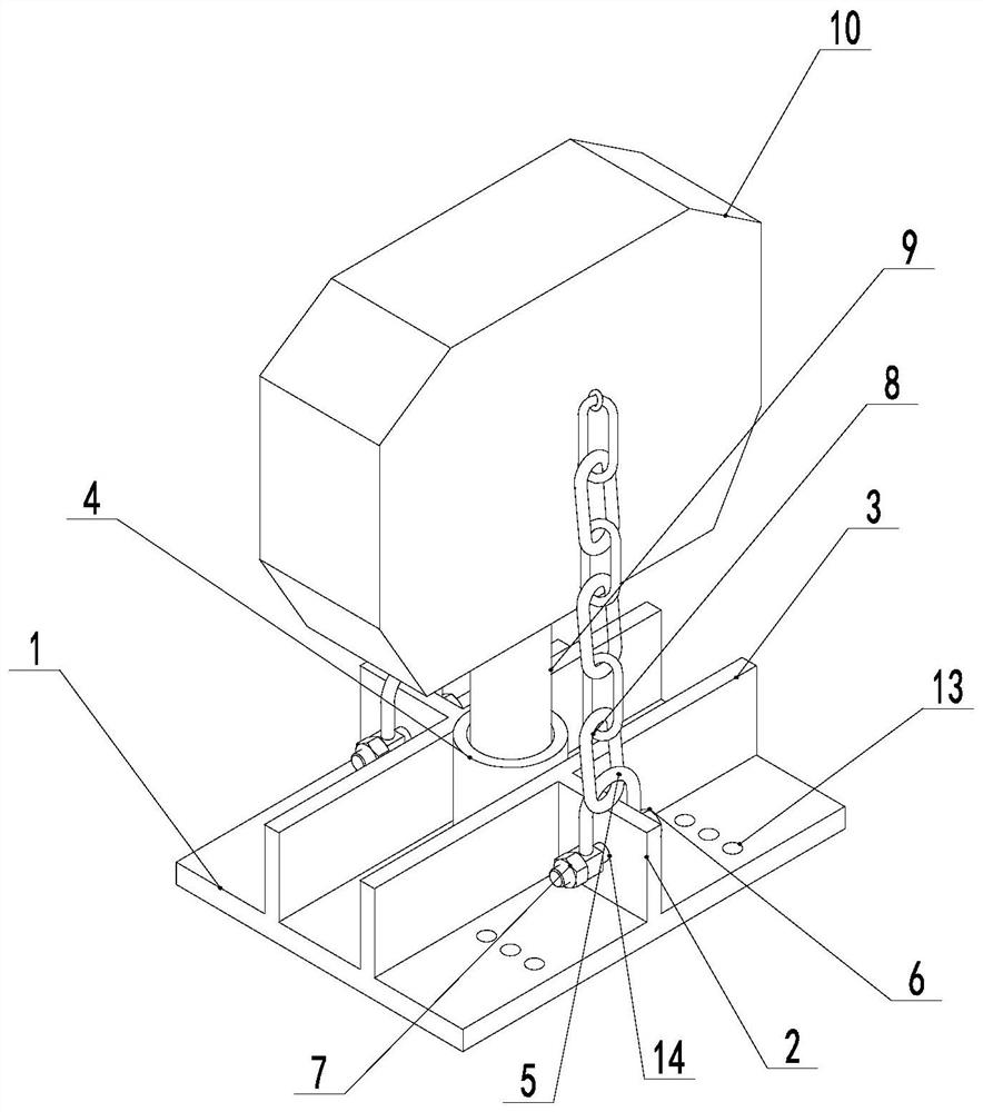
[0029] Such as figure 1 , 2 , 3, a rapid compaction device and method, comprising a compaction plate 1, a lifting plate 2, a reinforcement plate 3, a positioning cylinder 4, a connecting buckle 5, a bolt 6, a nut 7, an iron chain 8, a connecting hammer head 9, an impact Drill 10, the upper half and lower half of the tamping plate 1 are processed with exhaust pressure relief holes 13, and the exhaust pressure relief holes 13 are distributed on the upper and lower sides of the tamping plate 1, so that the tamping can be eliminated during the tamping operation. The air between the plate 1 and the foundation reduces the air resistance during the tamping process, which is beneficial to fully apply the tamping force to the foundation and improve the quality of tamping. The middle position of the tamping plate 1 is welded with the positioning cylinder 4...
PUM
Abstract
The invention discloses a rapid tamping device and a construction method. The rapid tamping device comprises a tamping plate, lifting plates, reinforcing plates, a positioning cylinder, connecting buckles, bolts, nuts, iron chains, a connecting hammer head and an impact drill. The device is characterized in that exhaust pressure relief holes are machined in the upper half part and the lower half part of the tamping plate, the positioning cylinder is welded to the middle position of the tamping plate, the two reinforcing plates are welded in the longitudinal direction of the tamping plate, thetwo lifting plates are welded in the middle transverse position of the tamping plate, a lifting hole is formed in the middle of each lifting plate, and the connecting buckles and the lifting plates are connected through the lifting holes, the bolts and the nuts; and the iron chains are arranged on the upper parts of the connecting buckles in a matched manner, the other ends of the iron chains aremounted on the impact drill, the connecting hammer head is inserted into the positioning cylinder for positioning, the tamping plate is hoisted through the iron chains on the two sides, and the otherend of the connecting hammer head is connected with a cantilever of an excavator. The rapid tamping device has the advantages of simple structure, convenient operation, strong applicability, no site limitation, high construction efficiency, short construction time, reduced working strength of operators and improved safety.
Description
technical field [0001] The invention relates to the field of building foundations, in particular to a rapid compaction device and a construction method. Background technique [0002] Building foundations are divided into natural foundations and artificial foundations. The foundation that can directly bear the load of the building without treatment is called the natural foundation, and conversely, the foundation that needs to be treated by the foundation treatment technology is called the artificial foundation. [0003] The artificial foundation is the foundation that can only be built after the soil quality of the natural soil layer is too weak or unfavorable geological conditions, and needs artificial reinforcement or treatment. In the case of poor geological conditions, such as slopes, sandy land or silt geology, or although the soil texture is good, but the upper load is too large, in order to make the foundation have sufficient bearing capacity, it is necessary to use a...
Claims
Application Information
Patent Timeline
Application Date:The date an application was filed.
Publication Date:The date a patent or application was officially published.
First Publication Date:The earliest publication date of a patent with the same application number.
Issue Date:Publication date of the patent grant document.
PCT Entry Date:The Entry date of PCT National Phase.
Estimated Expiry Date:The statutory expiry date of a patent right according to the Patent Law, and it is the longest term of protection that the patent right can achieve without the termination of the patent right due to other reasons(Term extension factor has been taken into account ).
Invalid Date:Actual expiry date is based on effective date or publication date of legal transaction data of invalid patent.