Check patentability & draft patents in minutes with Patsnap Eureka AI!

Wire sensor and monitoring system for dangerous rock monitoring

A pull wire sensor and pull wire technology, applied in the field of pull wire sensors, can solve the problems of high battery risk, short continuous use time, and insufficient accuracy, and achieve the effect of prolonging the voyage time, increasing the voyage time, and increasing the range

Active Publication Date: 2022-05-10
CHINA GEZHOUBA (GRP) FIRST ENG CO LTD +1
View PDF23 Cites 0 Cited by
  • Summary
  • Abstract
  • Description
  • Claims
  • Application Information

AI Technical Summary

Problems solved by technology

The biggest problem with the wire-type displacement sensor with this type of structure is that the accuracy is not enough. The specific performance is that in order to achieve a larger measurement range, it is necessary to use a larger-diameter winding wheel, and the detection of the wire displacement usually detects the winding The rotation angle of the wheel, but actually the winding diameter of each layer of the cable wound on the winding wheel is different, the length of the cable calculated from the angle of rotation has an error, and the length of the cable is even more uncontrollable when the winding sequence is chaotic.
Furthermore, the existing pull-wire displacement sensors require high energy consumption, and usually need to be equipped with an independent solar battery system for power supply, resulting in high costs, or a short duration of use, and the replacement of batteries in dangerous rock areas higher risk
The geotechnical monitoring in the prior art all adopts the pre-buried scheme, such as the scheme of Chinese patent document CN 102162234 A or CN109115168 A, but the construction method of the pre-buried scheme needs to excavate enough depth for the construction of dangerous rock monitoring more difficult

Method used


Image

  • Wire sensor and monitoring system for dangerous rock monitoring
  • Wire sensor and monitoring system for dangerous rock monitoring
  • Wire sensor and monitoring system for dangerous rock monitoring

Examples


Embodiment 1

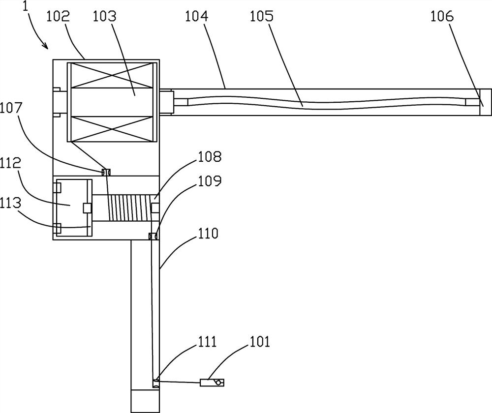
[0033] Such as Figure 1~6 Among them, a cable sensor for dangerous rock monitoring, which includes a winding wheel 103 and a cable rotating roller 108;

[0034] Such as image 3 As shown in , the winding wheel 103 is rotatably supported in the housing 102, the winding wheel 103 is used to wind the backguy 5, the winding wheel 103 is connected with the elastic device, so that the winding wheel 103 will pull the backguy 5 in one direction Tension;

[0035] The backguy roller 108 is rotatably supported in the housing 102, and the backguy 5 drawn from the winding wheel 103 is wound multiple times on the backguy roller 108, and is drawn out of the housing 102. Corner reading device. With this structure, by adopting the scheme that the winding wheel 103 and the wire-drawing roller 108 are separately arranged, the backguy will only be wound on one layer on the wire-drawing roller 108 all the time, thereby overcoming the problem in the prior art that the wire is wound on the wire-...

Embodiment 2

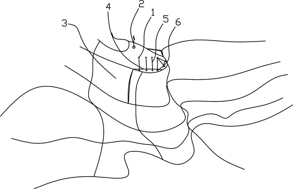
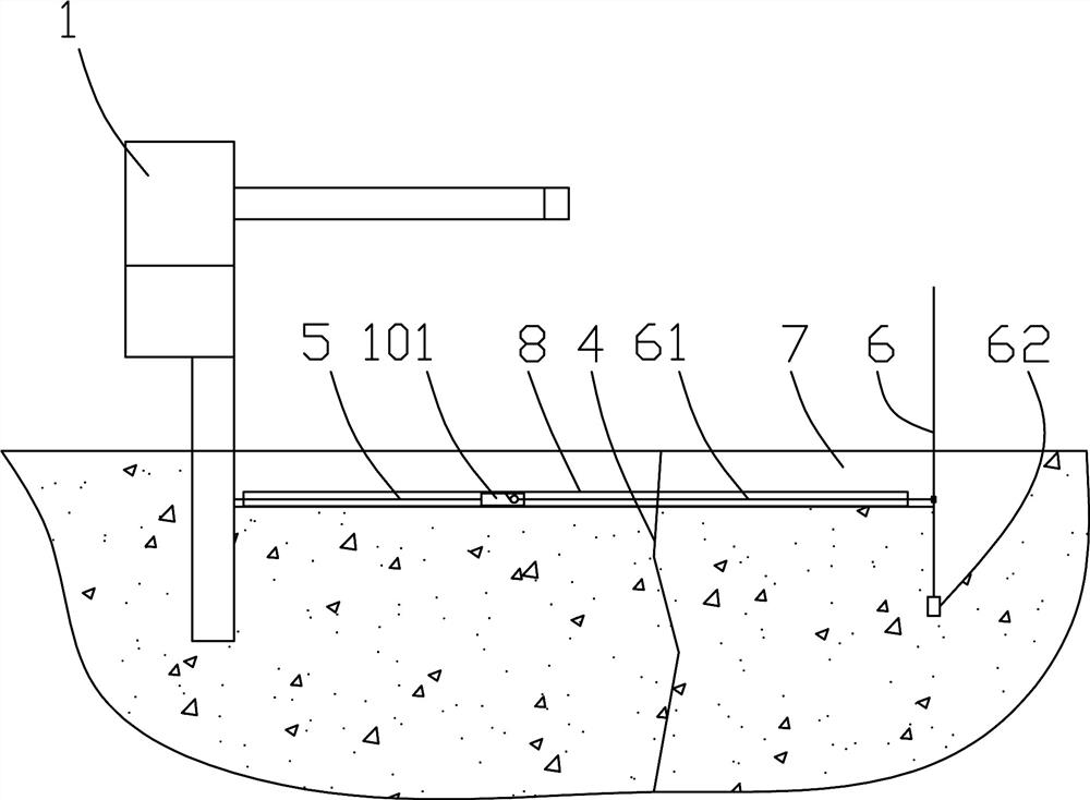
[0047] Such as figure 1 , 2 Among them, a monitoring system using the above-mentioned guy sensor for dangerous rock monitoring, it includes a guy sensor 1 and an anchor rod 6, the guy sensor 1 is fixed on the foundation side of the dangerous rock 3, and the anchor rod 6 is fixed on the dangerous rock 3 on the slip side;

[0048] One end of the connecting wire rope 61 is fixedly connected with the anchor rod 6, and the other end of the connecting wire rope 61 is fixedly connected with the connector 101 of the pull wire sensor 1;

[0049] An excavation groove 7 is arranged between the pull wire sensor 1 and the anchor rod 6 , the protection tube 8 is arranged in the excavation groove 7 , and the connecting wire rope 61 and the stay wire 5 penetrate into the protection tube 8 . Dangerous rock 3 in a certain place is mainly limestone, which is a hard rock with strong karstification. The weak base under the second-order cliff is the shale of the second member of the Maokou Format...


PUM


Abstract

The invention provides a cable sensor and a monitoring system for dangerous rock monitoring, which includes a cable winding wheel and a cable rotating roller; It is connected with the elastic device so that the winding wheel can tension the cable in one direction; the cable rotating roller is rotatably supported in the housing, and the cable drawn from the winding wheel is wound multiple times on the cable rotating roller and drawn out of the casing , Also provided with a reading device for detecting the rotation angle of the wire-drawing roller. The monitoring system includes a cable sensor and an anchor rod. The cable sensor is fixed on the foundation side of the dangerous rock, and the anchor rod is fixed on the slip side of the dangerous rock; there is an excavation groove between the cable sensor and the anchor rod, and the protective tube In the excavated groove, the connecting wire rope and the stay wire are passed into the protective tube. By adopting the scheme that the wire winding wheel is separated from the wire-drawing rotating roller, the error of the winding diameter of the wire-drawing in the prior art is overcome. Adopting the scheme of slotting arrangement, the construction is faster.

Description

technical field [0001] The invention relates to the field of cable sensors, in particular to a cable sensor and a monitoring system for dangerous rock monitoring. Background technique [0002] my country has a vast territory, with two-thirds of the country belonging to mountainous landforms. It is one of the countries most severely affected by landslides in the world, and the collapse of dangerous rocks will cause heavy losses to people's property and threaten their personal safety. According to the analysis of the geological environment, the formation of dangerous rocks includes two types of internal conditions and external conditions. The internal conditions include stratum lithology, slope structure, and high and steep free surfaces; the external conditions include rainfall, weathering, earthquakes, temperature, vegetation, and human engineering. activities etc. Commonly used monitoring methods include 1. Building reference points and monitoring points, and monitoring th...

Claims


Application Information

Patent Timeline
Patent Type & Authority Patents(China)
IPC IPC(8): G01B7/02G08C17/02
CPCG01B7/026G08C17/02
Inventor 孙向楠吴俊江孙花玲陈佩凡程东李希雷艳兵熊建武涂胜李光誉李新明文超
Owner CHINA GEZHOUBA (GRP) FIRST ENG CO LTD
Features
  • R&D
  • Intellectual Property
  • Life Sciences
  • Materials
  • Tech Scout
  • Unparalleled Data Quality
  • Higher Quality Content
  • 60% Fewer Hallucinations
Learn More