Self-powered current detection system and method of wide-flow-band power transmission line

A current detection and transmission line technology, applied in voltage/current isolation, measurement devices, measurement of electrical variables, etc., can solve problems such as inability to obtain energy, difficult energy sources, damage to energy extraction devices, etc., to achieve high-precision measurement, good Social and economic benefits, and the effect of reducing accident rates

Active Publication Date: 2020-09-11
NANJING NORMAL UNIVERSITY
View PDF8 Cites 2 Cited by
  • Summary
  • Abstract
  • Description
  • Claims
  • Application Information

AI Technical Summary

Problems solved by technology

At present, the traditional passive compensation method is gradually replaced by the active compensation method, which greatly improves the measurement level of the current detection device, but the energy source of the active part of the current detection device connected at high altitude is not easy. The inductive energy harvesting method has become a more suitable energy supply method, but when the line current fluctuates in a large range in the traditional inductive energy harvesting method, the energy harvesting device may not be able to obtain a certain amount of energy at a certain moment, or at another moment due to magnetic The oversaturation of the core will cause serious heat generation and damage the energy harvesting device itself

Method used


Image

  • Self-powered current detection system and method of wide-flow-band power transmission line
  • Self-powered current detection system and method of wide-flow-band power transmission line
  • Self-powered current detection system and method of wide-flow-band power transmission line

Examples


Embodiment Construction

[0029] The present invention will be further described below in conjunction with the accompanying drawings and specific embodiments. The following descriptions are only preferred embodiments of the present invention, and it should be pointed out that for those of ordinary skill in the art, some improvements and modifications can also be made without departing from the principle of the present invention. It should be regarded as the protection scope of the present invention.

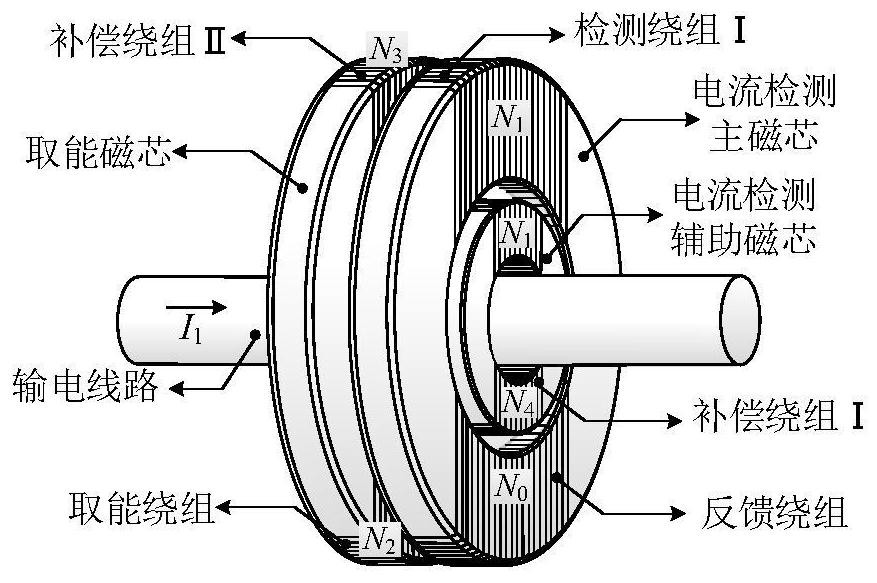
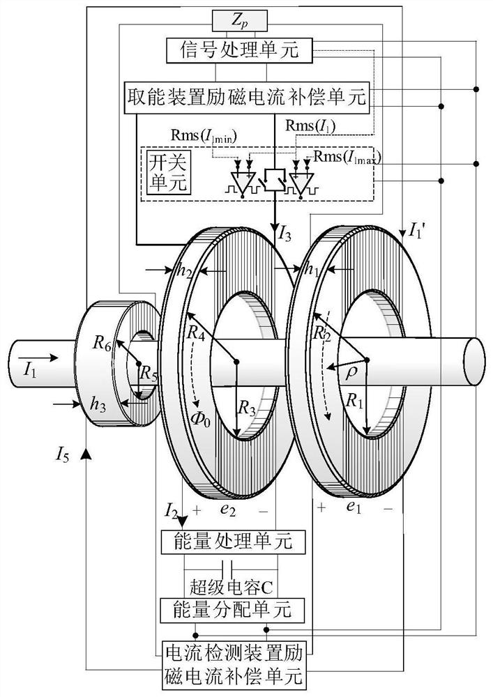
[0030] The system of the present invention includes a current detection device and an energy harvesting device. The current detection device is used for primary side current detection. The energy harvesting device provides electric energy for the current detection device. Both the current detection device and the energy harvesting device are set on the transmission line.

[0031] Such as figure 1 and figure 2 As shown, the current detection device includes a current detection main core, a current detec...


PUM


Abstract

The invention discloses self-powered current detection system and detection method of a wide-flow-band power transmission line. The system comprises a current detection device and an energy taking device which are arranged on a power transmission line in a sleeving manner. The current detection device is used for primary side current detection, and the energy taking device provides electric energyfor the current detection device; and the energy-taking magnetic core always works in a linear region through information transmission of the induction energy-taking device and the current detectiondevice and effective value and phase parameter configuration of the compensation exciting current. Compared with a traditional current detection device, the device has the following advantages: accurate current detection in a large current fluctuation range and real-time energy supply of the active circuit module are realized. The energy-taking magnetic core is enabled to always work in a linear area through information transmission of the induction energy-taking device and the current detection device in combination with key parameter configuration of the compensation exciting current so thatthe service life of the energy-taking magnetic core can be effectively prolonged and the accident rate of electrical equipment can be reduced.

Description

technical field [0001] The invention relates to the hook-up current detection and real-time power supply technology of high-voltage power transmission and transformation lines, in particular to a self-supply current detection system and detection method for wide-band power transmission lines. Background technique [0002] As an important carrier of power transmission, power transmission and transformation lines in power systems are of great significance for real-time current detection. For safety reasons, line current detection devices cannot be directly installed on line cables, so non-contact current detection devices have emerged as the times require. Due to the influence of the excitation current inside the magnetic core of the current detection device on the detection accuracy, it is difficult to have an inverse proportional relationship between the ratio of the primary and secondary current and the number of turns, so it is necessary to compensate the amplitude and phas...

Claims


Application Information

Patent Timeline
IPC IPC(8): G01R15/18
CPCG01R15/185
Inventor 王维许晨进王劼忞曾振炜王琦
Owner NANJING NORMAL UNIVERSITY
Why Eureka
Try Eureka