Locally heat-treated and hardened screw

A local quenching and screw technology, used in heat treatment furnaces, heat treatment equipment, screws, etc., can solve problems such as screw head fracture, screw deformation, and sudden head breakage.

Inactive Publication Date: 2003-07-30
ILLINOIS TOOL WORKS INC
View PDF7 Cites 0 Cited by
  • Summary
  • Abstract
  • Description
  • Claims
  • Application Information

AI Technical Summary

Problems solved by technology

However, this quenching may cause the screw head and upper half to become so brittle that (1) the screw head breaks due to screw displacement when excessive torque is applied; (2) hydrogen embrittlement (if the screw is plated) And (3) the head is suddenly broken, which is caused by the thermal expansion and contrac

Method used


Image

  • Locally heat-treated and hardened screw
  • Locally heat-treated and hardened screw
  • Locally heat-treated and hardened screw

Examples


Embodiment Construction

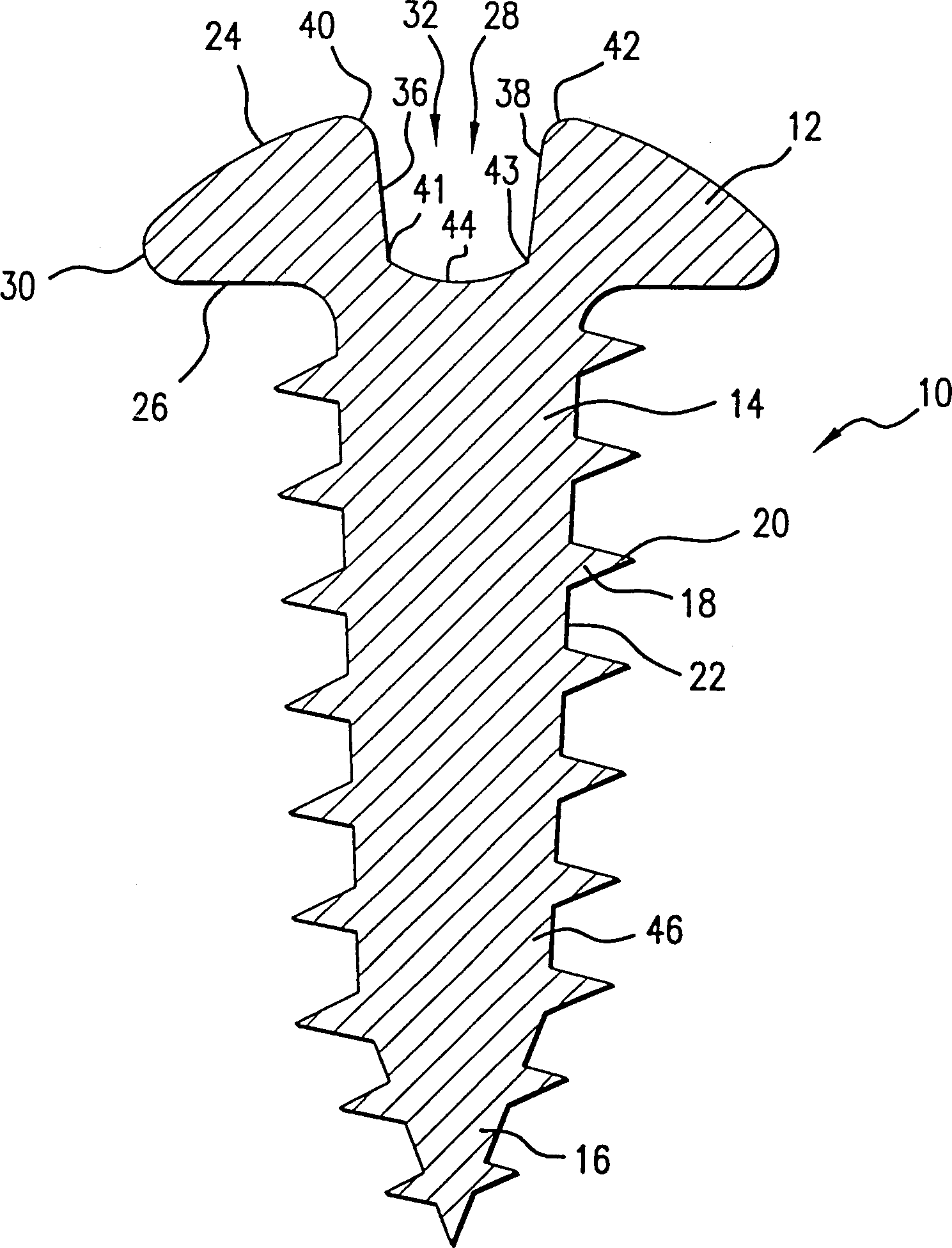
[0020] refer to figure 1 The carbon steel screw 10 of the present invention has a head 12, a screw portion 14 below the head and a screw point 16 at one end of the screw portion opposite the head. A plurality of threads or threads 18 having cusps 20 and interdental grooves 22 wrap around the screw portion 14 and screw tip 16 .

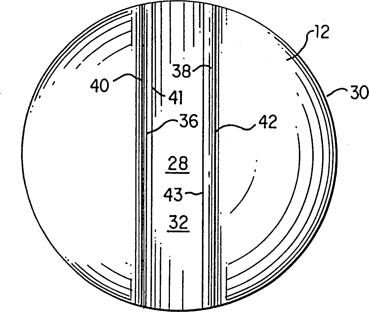
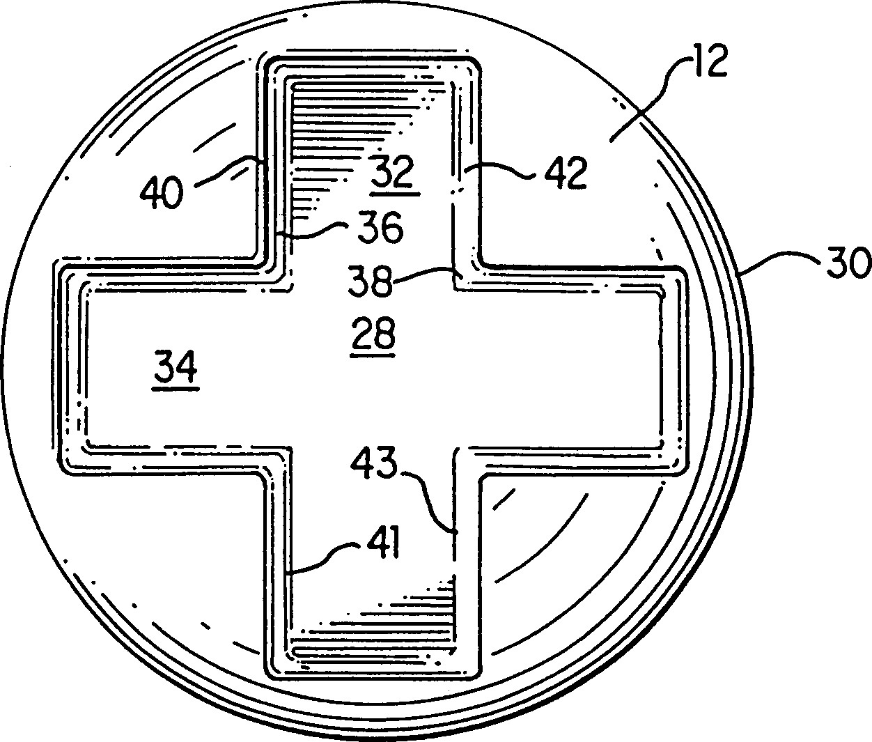
[0021] refer to Figure 1-3 , the head 12 has a top surface 24 , a bottom 26 , a central region 28 and an outer rim 30 . The central area 28 includes an in-line recess 32 suitable for receiving a standard screwdriver or similar driving tool or suitable for receiving a Phillips TM A pair of intersecting grooves 32 and 34 of a screwdriver or similar driving tool designed for cross-shaped grooves.

[0022] Each groove is defined by a pair of opposed generally upstanding walls 36 and 38 which intersect top surface 24 at edges 40 and 42 and groove bottom 44 at intersection lines 41 and 43 . The groove depth is the distance between the edges 40 and 42 an...


PUM


Abstract

A carbon steel screw has one or more portions which have been selectively hardened by selective heat treatment and quenching. In one embodiment, an upper portion of the screw head is selectively hardened to prevent or reduce damage when torque is applied using a driving tool. In the other embodiment, the screw tip may be selectively hardened for more effective penetration into a substrate. Preferably, the selectively heated portions are selectively quenched to reduce or avoid distortion.

Description

technical field [0001] This invention relates to carbon steel screws and similar fasteners which are partially hardened to provide desired properties and behavior, and methods of making such partially hardened screws. Background technique [0002] Stainless steel screws with partially quenched portions are disclosed in US Patent No. 3,376,780 to Tanczyn. The stainless steel screw disclosed by Tanczyn has partially hardened threads and a partially hardened head adapted to be inserted into a screwdriver. These areas are harder than the rest of the screw. The stainless steel screw contains no more than 0.20wt% (weight percent, the same below) of carbon, 10-25wt% of chromium, 5-20wt% of nickel, 1-5wt% of copper and 0.25-2.5wt% of aluminum. Quenching is accomplished by cold working stainless steel at about 700-900°F and age quenching at 1050-1250°F. This quenching is greatest in areas where cold work is greatest. [0003] US Patent No. 4,295,351 to Bjorklund et al. discloses ...

Claims


Application Information

Patent Timeline
IPC IPC(8): F16B25/00C21D9/00F16B19/00F16B35/00
CPCC21D2211/008C21D9/0093C21D2221/01F16B19/00
Inventor 马克·D·拜尔威廉姆·A·斯普林迈克·斯塔罗兹希特斯基S·雷斯·尤尔哈森
Owner ILLINOIS TOOL WORKS INC
Why Eureka
Try Eureka