Motor rotor punching sheet and motor rotor assembly system

A motor rotor and rotor punching technology, which is applied to electrical components, electromechanical devices, electric components, etc., can solve the problems of large rotor centrifugal force and motor burnout

Inactive Publication Date: 2020-09-11
ANHUI JIANGHUAI AUTOMOBILE GRP CORP LTD
View PDF5 Cites 5 Cited by
  • Summary
  • Abstract
  • Description
  • Claims
  • Application Information

AI Technical Summary

Problems solved by technology

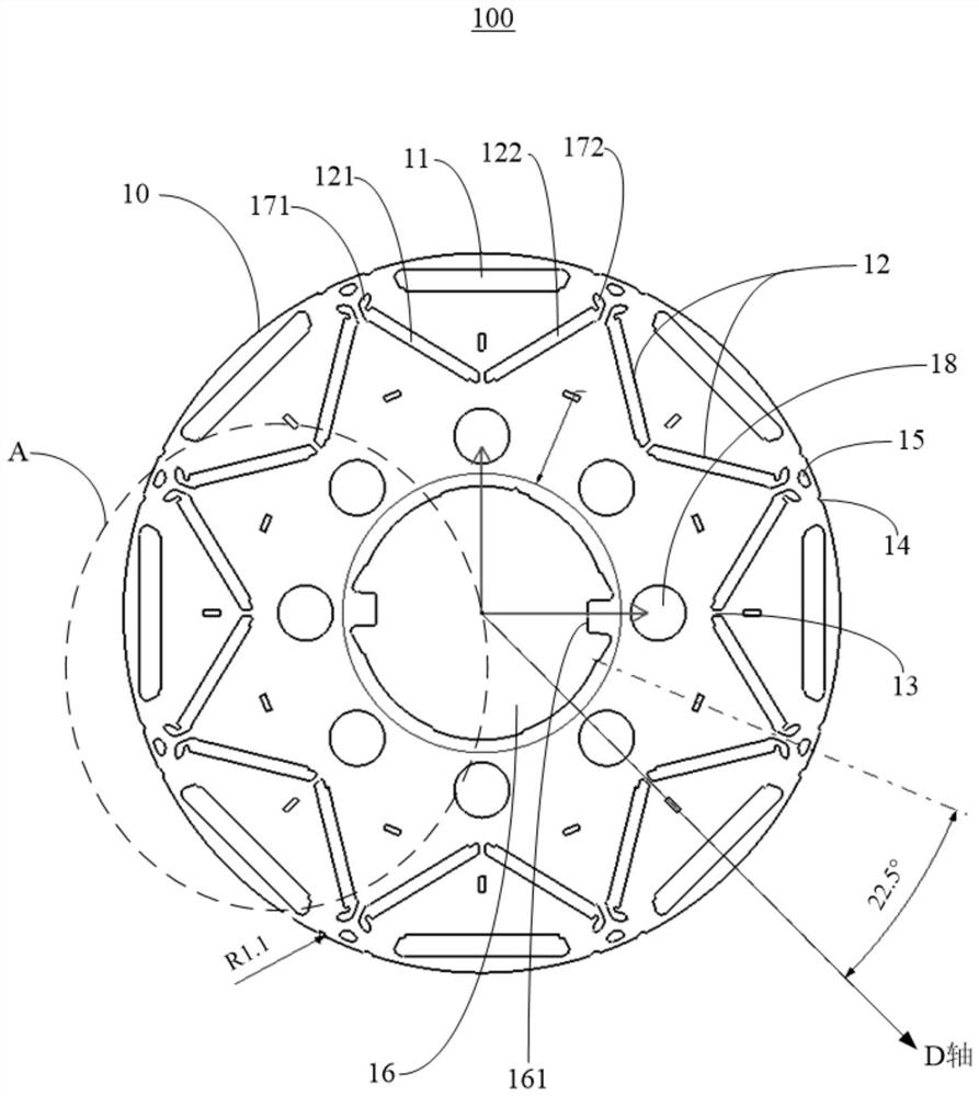
For example, when the vehicle continues to run at high speed, as the temperature of the rotor increases, the yield strength of the rotor punching gradually decreases, but the centrifugal force of the rotor rotating at high speed is relatively large. When the yield of the rotor punching caused by the centrifugal force is greater than that of the punching itself When the yield strength is lower than the yield strength, the outer circle of the rotor punch will bulge, causing the stator and rotor of the motor to sweep. In severe cases, the motor may catch fire and burn down

Method used


Image

  • Motor rotor punching sheet and motor rotor assembly system
  • Motor rotor punching sheet and motor rotor assembly system
  • Motor rotor punching sheet and motor rotor assembly system

Examples


Embodiment Construction

[0037] The following will clearly and completely describe the technical solutions in the embodiments of the present invention with reference to the accompanying drawings in the embodiments of the present invention. Obviously, the described embodiments are only part of the embodiments of the present invention, not all of them. Based on the embodiments of the present invention, all other embodiments obtained by persons of ordinary skill in the art without creative efforts fall within the protection scope of the present invention.

[0038] It should be noted that if there is a directional indication (such as up, down, left, right, front, back...) in the embodiment of the present invention, the directional indication is only used to explain the position in a certain posture (as shown in the accompanying drawing). If the specific posture changes, the directional indication will also change accordingly.

[0039] In addition, if there are descriptions involving "first", "second" and ...


PUM


Abstract

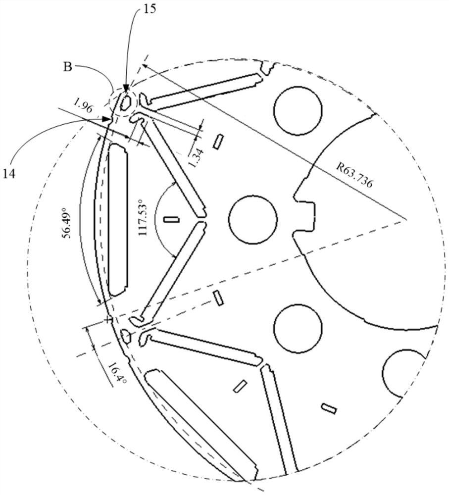
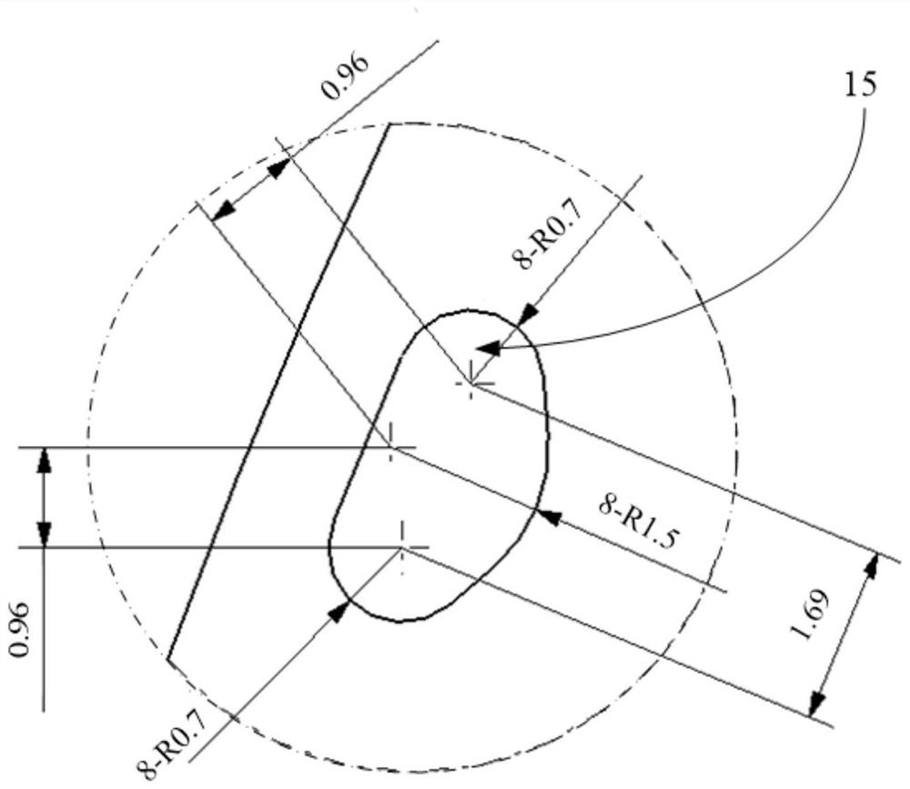
The invention discloses a motor rotor punching sheet and a motor rotor assembly system. The motor rotor punching sheet comprises a rotor punching sheet body, wherein a plurality of groups of magneticsteel grooves, a plurality of groups of auxiliary grooves and a plurality of harmonic wave removing holes are formed in the rotor punching sheet body, the plurality of groups of magnetic steel groovesare arranged at intervals along the circumferential direction of the rotor punching sheet body, each group of magnetic steel grooves comprises a first magnetic steel groove and a second magnetic steel groove, the first magnetic steel groove and the second magnetic steel groove are sequentially arranged at intervals from the edge to the center of the rotor punching sheet body, the second magneticsteel groove comprises a first section and a second section, and a magnetic bridge is arranged between the first section and the second section; the plurality of groups of auxiliary grooves are arranged corresponding to the plurality of groups of magnetic steel grooves, and each group of auxiliary grooves comprises two open grooves which are correspondingly positioned at two ends of one first magnetic steel groove; and the plurality of harmonic wave removing holes are correspondingly arranged between every two adjacent first magnetic steel grooves. The motor rotor punching sheet solves the problems of weak strength and high risk caused by the temperature rise of the motor rotor and the reduction of the yield strength of the rotor punching sheet in the continuous height rotation process ofthe motor.

Description

technical field [0001] The invention relates to the technical field of motors, in particular to the field of motor rotors, in particular to a motor rotor stamping and a motor rotor assembly system. Background technique [0002] Motors and motor controllers are the core components of pure electric cars, and their performance directly determines the performance of the vehicle. The motor rotor is the most important core component of the motor. Its structural characteristics determine the power and torque performance of the motor, and because it is in a high-speed rotating state during operation, it has high requirements for strength. [0003] There are various forms of motor rotor designs, but they are basically positive rotor designs based on motor power, torque and strength under normal working conditions; because the current motor test verification is not very sufficient, no risk can be identified; With the gradual improvement of battery life of pure electric vehicles, more...

Claims


Application Information

Patent Timeline
Patent Type & Authority Applications(China)
IPC IPC(8): H02K1/27
CPCH02K1/276H02K2213/03
Inventor 李大伟沙伟于占斌刘悦新张俊来
Owner ANHUI JIANGHUAI AUTOMOBILE GRP CORP LTD
Why Eureka
Try Eureka