Efficient heat dissipation system for pole coil of hydro-generator

A hydro-generator and heat dissipation system technology, applied in electrical components, electromechanical devices, electric components, etc., can solve the problems of poor heat dissipation effect of magnetic poles, uneven temperature, complex structure of heat dissipation system, etc., to reduce ventilation loss and ensure uniformity Heat dissipation, avoid the effect of complex structure

Active Publication Date: 2020-09-11
浙江富春江水电设备有限公司
View PDF6 Cites 2 Cited by
  • Summary
  • Abstract
  • Description
  • Claims
  • Application Information

AI Technical Summary

Problems solved by technology

[0006] The purpose of the present invention is to solve the problem of poor heat dissipation effect and uneven temperature of the rotor magnetic poles existing in the cooling system of the hydro-generator, and to provide a high-efficiency heat dissipation system for the magnetic pole coil of the hydro-generator, which can effectively improve the The heat dissipation effect of the rotor magnetic poles can significantly reduce the ventilation loss, improve the efficiency of heat dissipation and cooling, ensure the uniform heat dissipation of the generator set, and avoid the complex structure of the heat dissipation system

Method used


Image

  • Efficient heat dissipation system for pole coil of hydro-generator
  • Efficient heat dissipation system for pole coil of hydro-generator
  • Efficient heat dissipation system for pole coil of hydro-generator

Examples


Embodiment Construction

[0037] The present invention will be further described below in conjunction with the accompanying drawings and specific embodiments.

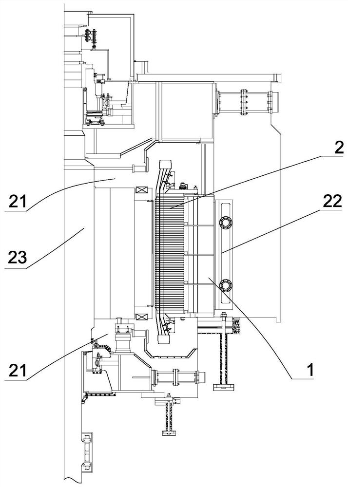
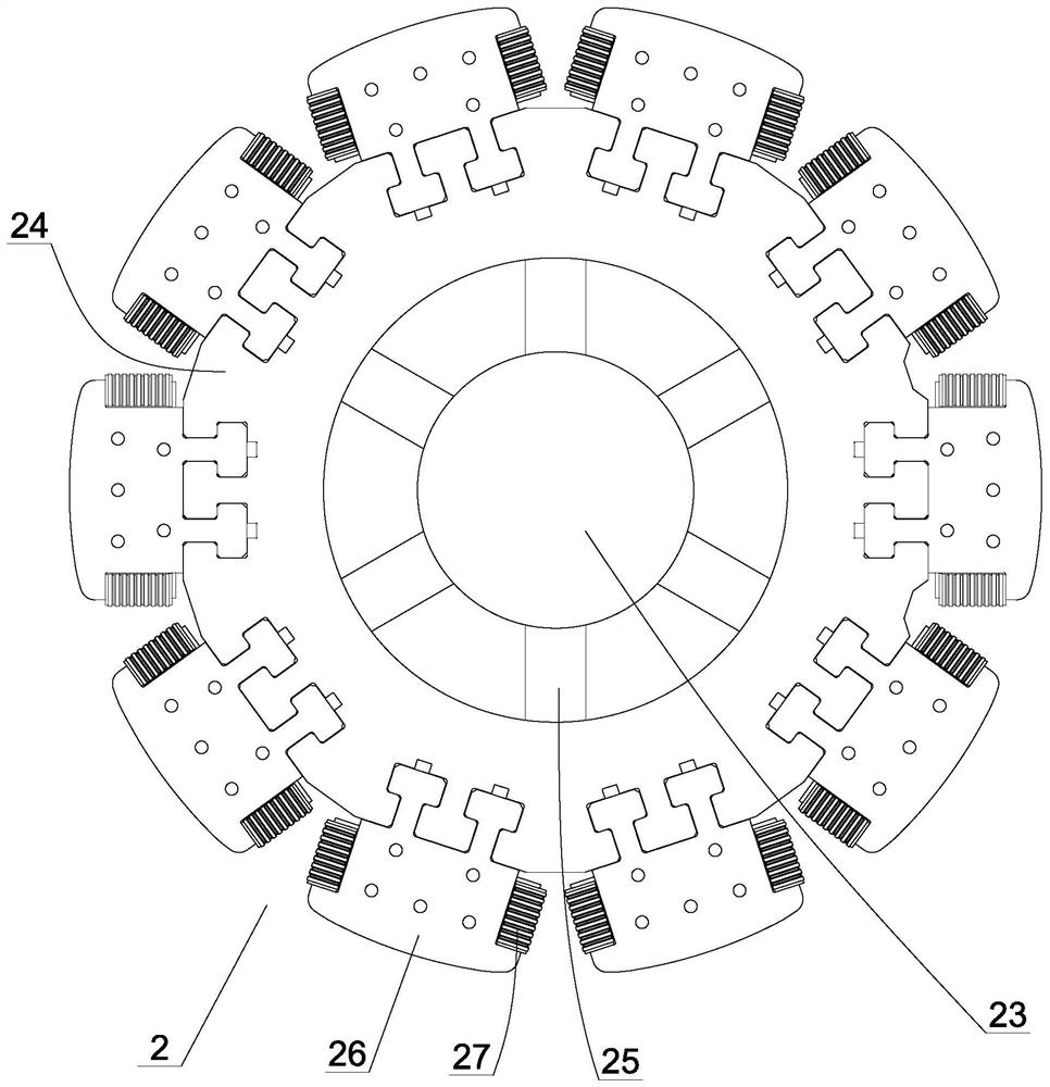
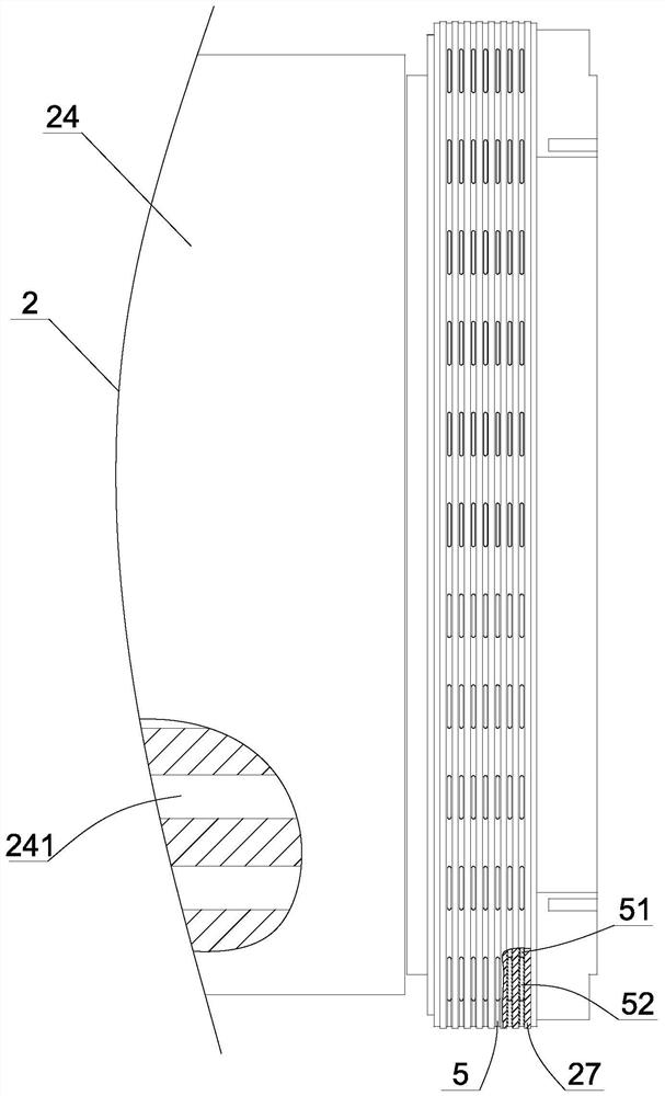
[0038] Such as figure 1 As shown, a high-efficiency heat dissipation system for the magnetic pole coil of a hydro-generator includes a stator 1, a rotor 2 rotatably arranged in the stator, and a cooling and heat dissipation system (not shown in the figure) for cooling and driving the cooling air, such as figure 2 As shown, the rotor includes a middle shaft 23, a peripheral yoke 24, a bracket 25 for connecting the shaft and the yoke, a number of magnetic poles arranged around the yoke, the magnetic poles include an iron core 26, and a Several layers of rectangular frame-shaped copper bars 27. In order to facilitate the heat dissipation and cooling of the rotor and stator, such as image 3 As shown, we need to respectively set several radial ventilation holes 241 arranged at intervals along the axial direction on the yoke, the iron core and th...


PUM


Abstract

The invention discloses an efficient heat dissipation system for a pole coil of a hydro-generator. The system comprises a stator, a rotor and a cooling system. The rotor comprises a rotating shaft, amagnet yoke, a bracket for connecting the rotating shaft and the magnet yoke, a plurality of iron cores, and a plurality of layers of copper bars arranged on the iron cores. The magnet yoke, the ironcore and the stator are respectively provided with a plurality of radial ventilation holes. The middle part of the outer side of the stator is an air outlet end. The cooling system is connected with the air inlet end and the air outlet end through pipelines. A ventilation turn is arranged between every two adjacent layers of copper bars, axial ventilation holes which extend in the axial directionof the rotor and penetrate through the air inlet ends of the two ends are formed in the ventilation turns, a plurality of radial heat dissipation holes which penetrate through the axial ventilation holes are formed in the outer sides of the ventilation turns, and the areas of the radial heat dissipation holes are gradually increased from the two ends of the rotor to the middle of the rotor. According to the invention, the heat dissipation effect of the rotor magnetic pole can be effectively improved, the ventilation loss is reduced, the heat dissipation and cooling efficiency is improved, andthe complex structure of a heat dissipation system can be avoided.

Description

technical field [0001] The invention relates to the technical field of hydraulic generators, in particular to a high-efficiency cooling system for magnetic pole coils of hydraulic generators. Background technique [0002] With the enhancement of people's awareness of energy conservation and environmental protection, hydropower as a green energy is being vigorously developed. In the field of hydropower, the water turbine is a key part, which usually includes a stator, a rotor rotatably arranged in the stator, and a rotor for driving the rotor. Rotating runner, wherein the runner is set in a volute, and the volute is set in the machine pit. The runner includes several blades. One side is provided with a water inlet pipe with an opening aligned with the water-facing surface of the blade, and the other side of the volute is provided with a water outlet pipe. The rotor includes a rotor shaft connected to the rotor drive, a rotor yoke connected to the rotor shaft through a rotor ...

Claims


Application Information

Patent Timeline
Patent Type & Authority Applications(China)
IPC IPC(8): H02K9/20H02K9/10H02K1/22H02K1/20H02K1/32
CPCH02K1/20H02K1/22H02K1/32H02K9/10H02K9/20H02K2213/03
Inventor 马建峰刘思靓毛继业
Owner 浙江富春江水电设备有限公司
Why Eureka
Try Eureka