Switching value signal control circuit and control method
A switching signal and control circuit technology, applied in electronic switches, electrical components, pulse technology, etc., can solve problems such as uncontrolled, switching signal malfunction, hazards, etc.
- Summary
- Abstract
- Description
- Claims
- Application Information
AI Technical Summary
Problems solved by technology
Method used
Image
Examples
Embodiment 1
[0071] How to ensure that the switching signal of the whole process can be output stably, reliably and safely is the key to reducing the misoperation of the industrial automation field control system.
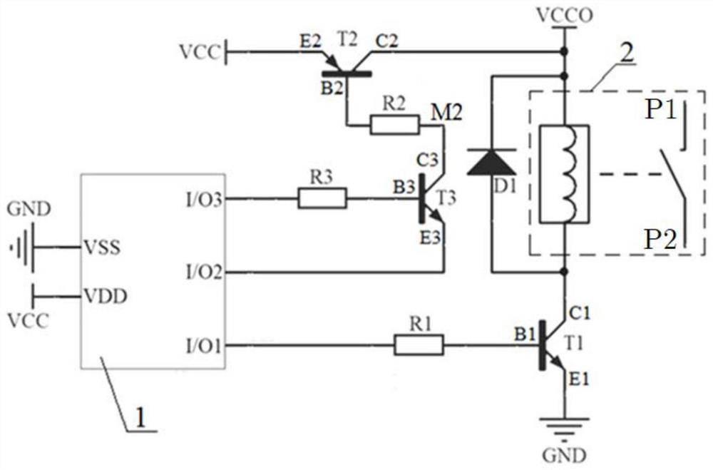
[0072] The present invention provides a switching value signal control circuit, including a microprocessor 1, a first switching tube, and a relay 2. The microprocessor 1 has a first I / O interface, a second I / O interface, a third I / O interface, and a second I / O interface. O interface, the control end of the first switching tube is electrically connected to the first I / O interface, and a pair of normally open contacts (P1, P2) of the relay 2 are connected to the controlled circuit of the switch signal control circuit , the switch signal control circuit further includes a second switch tube and a switch tube drive unit. A pair of normally open contacts of the relay 2 are turned on or off, so that the controlled circuit is turned on or off.
[0073] The first switch tube, the seco...
Embodiment 2
[0095] As shown in Figure 2(b), the difference between Embodiment 2 and Embodiment 1 is that the triode T1, triode T2, and triode T3 are NPN type, NPN type, and PNP type respectively, and the collector C1 of the triode T1 The emitter E1 and the emitter E1 of the triode T2 are electrically connected to the ground GND respectively, and the collector C2 of the triode T2 is electrically connected to the first power supply terminal VCC through the coil of the relay 2 .
[0096] In Embodiment 2, through the structures of the triode T1, the triode T2, and the triode T3 and the above-mentioned connection relationship, it is possible to:
[0097] (A1) When the outputs of the second I / O interface I / O2 and the third I / O interface I / O3 are both at high level, the transistor T3 is turned off, so that the transistor T2 is turned off, so that the relay 1 A pair of normally open contacts cannot be connected, so as to avoid malfunctions caused by the uncertain and uncontrolled state of the I / O...
Embodiment 3
[0103] As shown in Figure 2(c), the difference between Embodiment 3 and Embodiment 1 is that the triode T1, triode T2, and triode T3 are PNP type, PNP type, and NPN type respectively, and the collector of the triode T1 passes through The coil of the relay 2 is electrically connected to the ground GND, and the collector and emitter of the triode T2 are respectively electrically connected to the emitter of the triode T1 and the first power supply terminal VCC.
[0104] (A1) When the output of the second I / O interface and the third I / O interface are both at high level, the transistor T3 is turned off, so that the transistor T2 is turned off, so that a pair of normally open contacts of the relay 1 The points cannot be connected, so as to avoid the misoperation caused by the uncertain and uncontrolled state of the I / O after the microprocessor is just started;
[0105] (B1) When the output of the second I / O interface and the third I / O interface are both at low level, the transistor ...
PUM
 Abstract
Description
Claims
Application Information
 - R&D
- Intellectual Property
- Life Sciences
- Materials
- Tech Scout
- Unparalleled Data Quality
- Higher Quality Content
- 60% Fewer Hallucinations
Browse by: Latest US Patents, China's latest patents, Technical Efficacy Thesaurus, Application Domain, Technology Topic, Popular Technical Reports.
© 2025 PatSnap. All rights reserved.Legal|Privacy policy|Modern Slavery Act Transparency Statement|Sitemap|About US| Contact US: help@patsnap.com


