Extraction fitting for liquid containers

A technology for liquid containers and accessories, applied in the field of extraction accessories for liquid containers, to achieve the effect of increasing the contact surface and reducing the number of pieces

Active Publication Date: 2020-09-11
PROTECHNA SA
View PDF17 Cites 0 Cited by
  • Summary
  • Abstract
  • Description
  • Claims
  • Application Information

AI Technical Summary

Problems solved by technology

[0005] The corresponding combination of properties of the material for the valve body required in known extraction fittings therefore limits the choice of material from the outset.

Method used


Image

  • Extraction fitting for liquid containers
  • Extraction fitting for liquid containers
  • Extraction fitting for liquid containers

Examples


Embodiment Construction

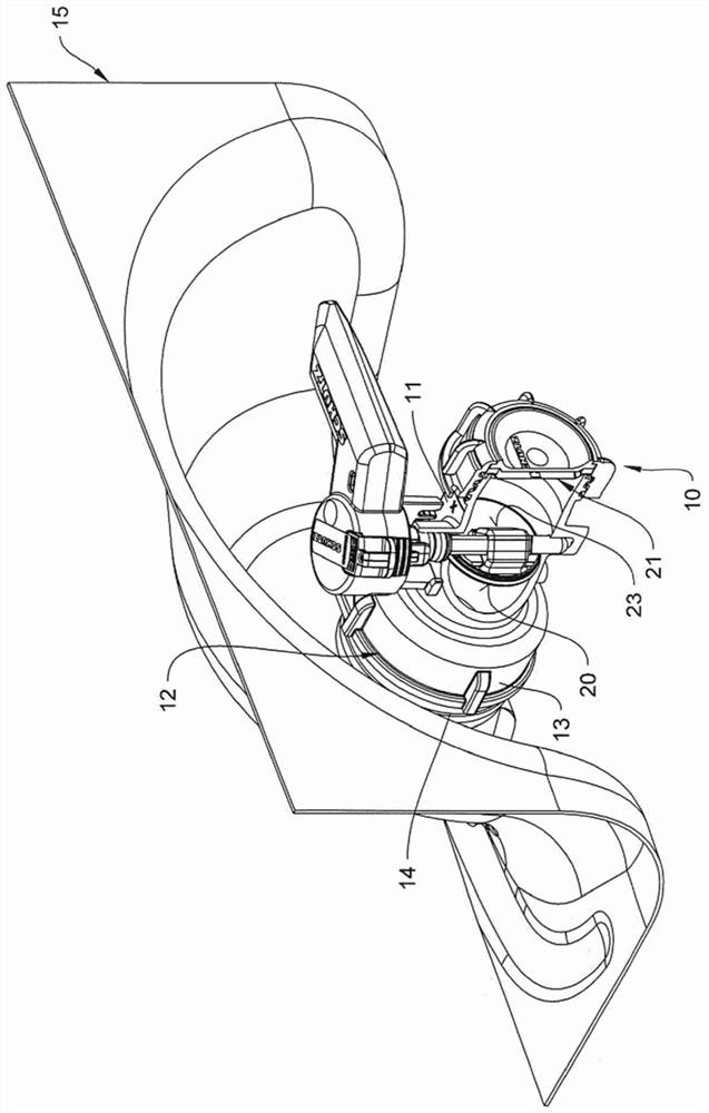
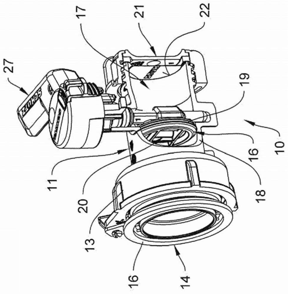
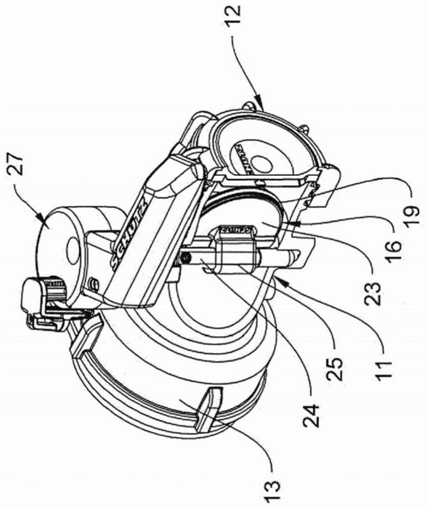
[0028] figure 1 The extraction fitting 10 is shown, which has a fitting housing 11 which is connected at the inflow end 12 by means of a union nut 13 to an outlet connection 14 which is arranged on a liquid container 15 ,exist figure 1 Only the accessory connection area is shown in . as in figure 1 A liquid container 15 of the type shown in is, for example, a container produced in blow molding, which is a component of an Intermediate Bulk Container (IBC) and is arranged as an inner container in a cage arranged on a pallet.

[0029] such as especially figure 2 As shown, in the case of the shown exemplary embodiment, the extraction fitting 10 is formed in combination with the outflow connection 14 formed independently of the liquid container 15 as an assembly unit, which can be connected to the liquid container 15 by means of Between the connection flange 16 of the outflow connection 14 formed as a welded connection and the outflow formed in the liquid container 15 figure ...


PUM


Abstract

The invention relates to an extraction fitting (10) for liquid containers (15), particularly for connecting to the throat (14) or the outlet of a transport and storage container for liquids, comprising a fitting housing (11) in which a valve body that can be pivoted with a valve shaft and is used to open and close a flow cross-section of an outflow pipe is arranged, the valve body comprising a valve seal which is at least partially arranged on a peripheral edge of the valve body in such a way that, in a shut-off position of the valve body, a valve gap formed between the valve body and an innerwall of the outflow pipe is sealed by the valve seal in a radial seal plane, and at least one inner side (20) of the valve body, facing a liquid volume, for shut-off, is covered by the valve seal such that a liquid contact surface arranged on the inner side (20) is embodied by the valve seal.

Description

technical field [0001] The invention relates to a dispensing fitting for liquid containers, in particular for connection to a spout or spout of a transport and storage container for liquids, which has a fitting housing in which a A valve body pivotable by means of a valve shaft for opening and closing a flow-through cross-section of an outlet pipe of a fitting housing, wherein the valve body has a valve seal which is arranged at least partially in a ring of the valve body On the peripheral edge, in the shut-off position of the valve body, the valve gap formed between the valve body and the inner wall of the outlet pipe is sealed by the valve seal along a radial sealing plane. Background technique [0002] In order to be able to achieve a reliable sealing of the through-flow cross-section, it is necessary firstly that the valve body is sufficiently rigid to be able to transmit the torque applied to the valve body via the valve shaft without the valve body being connected ther...

Claims


Application Information

Patent Timeline
Patent Type & Authority Applications(China)
IPC IPC(8): F16K1/20F16K1/36
CPCF16K1/2014F16K1/36F16K1/205F16K1/20F16K27/06
Inventor 蒂洛·克莱因
Owner PROTECHNA SA
Why Eureka
Try Eureka