A machine tool waste chute capable of bidirectional unloading

A waste chute and machine tool technology, applied in metal processing machinery parts, separation methods, filtration and separation, etc., can solve the problems of machine tool spindle deformation, high risk factor, large chip volume, etc., achieving low cost, safe operation, and avoiding emergency stop. Effect

Active Publication Date: 2022-04-05
平湖市成功机械有限公司
View PDF5 Cites 0 Cited by
  • Summary
  • Abstract
  • Description
  • Claims
  • Application Information

AI Technical Summary

Problems solved by technology

[0004] When the machine tool is cutting, with the rotation of the workpiece, the cut chips are recovered through the lower trough, and the recovered chips can be recast. However, we found in actual processing that due to the relatively Large, so the amount of chips generated is large, and the chips are mainly spiral chips. As the workpiece rotates, some of these chips will wrap around the workpiece, and some of the chips that fall into the chute will be rolled up by the workpiece again. , the tool movement will contact this chip, causing the tool to be broken, or the spindle of the machine tool to be deformed
[0005] However, if the chips in the trough are manually cleaned, the risk factor during cleaning is higher due to the chips falling from above.

Method used


Image

  • A machine tool waste chute capable of bidirectional unloading
  • A machine tool waste chute capable of bidirectional unloading
  • A machine tool waste chute capable of bidirectional unloading

Examples


Embodiment 1

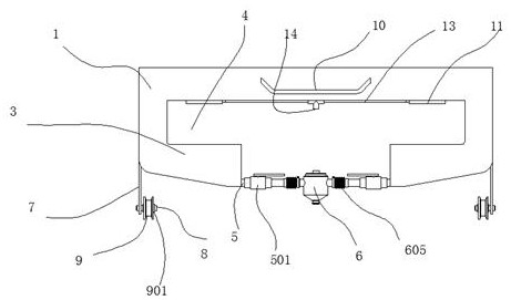
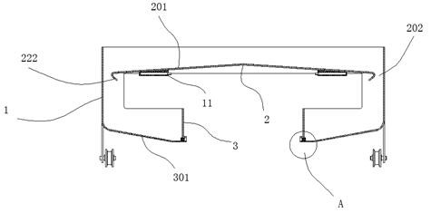
[0038]A machine tool waste chute capable of two-way unloading, comprising a trough body 1 welded by stainless steel plates with a thickness of 3 mm, a material distribution plate 2 is arranged inside the trough body 1, and the material distribution plate 2 and The grooves 1 are fixed by welding, and the formed welds are glued and sealed with glass glue. The upper end of the material distribution plate 2 is provided with two material guide surfaces 201, and the material guide surfaces 201 face the The side of the tank body 1 is inclined, a blanking gap 202 is formed between the outer side of the material guide surface 201 and the inner surface of the tank body 1, and a blanking gap 202 corresponding to the blanking material is provided below the tank body 1. The receiving chute 3 of the gap 202, the receiving trough 3 has an inclined first material guide surface 301, the first material guide surface 301 is inclined towards the center of the tank body 1, at the center of the tank...

Embodiment 2

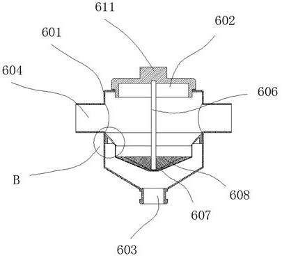
[0040] The filter device 6 includes a casing 601, the upper end of the casing 601 is screwed with a casing cover 602, the bottom of the casing 601 is provided with a first outlet pipe 603 for leading out the cooling liquid, and the outer wall of the casing 601 is provided There are two connecting pipes 604 corresponding to the outlet pipe 5, a folding pipe 605 is installed between the connecting pipe 604 and the outlet pipe 5, and a magnetic steel rod 606 is inserted at the bottom axis of the shell cover 602 The lower end of the magnetic steel rod 606 is provided with a conical cover 607 for collecting and cooling, and a plurality of filter screens 608 are annularly provided on the conical surface of the conical cover 607 .

[0041] The upper end of the cover 602 is integrated with a polygonal force-receiving part 611 , when the cover 602 needs to be opened, a torque can be applied to the force-receiving part 611 with a wrench or other tools; the above-mentioned structure is co...

Embodiment 3

[0045] A handle 10 is welded on the front end of the tank body 1; the handle 10 is conveniently arranged to pull the tank body 1 back and forth.


PUM


Abstract

The invention discloses a machine tool waste chute capable of bidirectional unloading. As the side of the tank body is inclined, a blanking gap is formed between the outer side of the material guide surface and the inner surface of the tank body, and a receiving material corresponding to the blanking gap is arranged below the tank body. trough, the receiving chute has an inclined first material guide surface, the first material guide surface is inclined towards the center of the trough, and the front and rear ends of the trough are provided with The operating gap used; this product can realize chip cleaning without stopping the machine.

Description

technical field [0001] The invention relates to a machine tool waste chute capable of bidirectional unloading. Background technique [0002] Machining refers to the process of changing the shape or performance of a workpiece through a mechanical device. According to the difference in processing method, it can be divided into cutting processing and pressure processing. [0003] A lathe is a machine tool that mainly uses a turning tool to turn a rotating workpiece. Drills, reamers, reamers, taps, dies and knurling tools can also be used for corresponding processing on the lathe. Lathes are mainly used to process shafts, discs, sleeves and other workpieces with rotating surfaces, and are the most widely used machine tools in machinery manufacturing and repair factories. [0004] When the machine tool is cutting, with the rotation of the workpiece, the cut chips are recovered through the lower trough, and the recovered chips can be recast. However, we found in actual processi...

Claims


Application Information

Patent Timeline
Patent Type & Authority Patents(China)
IPC IPC(8): B23Q11/00B01D29/03B01D29/11B01D29/56
CPCB23Q11/0067B01D29/035B01D29/11B01D29/56
Inventor 张开良张利英
Owner 平湖市成功机械有限公司
Why Eureka
Try Eureka