Combined plastic mold for cast-in-situ mold plate shaping and with fastening structure and processing process thereof
What is Al technical title?
Al technical title is built by PatSnap Al team. It summarizes the technical point description of the patent document.
A technology of locking structure and plastic mould, which is applied in the direction of mold fixing device, mold auxiliary parts, unloading device, etc. It can solve the problems of large number of clips, long installation and disassembly time, etc., so as to achieve not easy tripping, multiple installation and disassembly the effect of time
Inactive Publication Date: 2020-09-15
嘉兴市通程塑业有限公司
View PDF17 Cites 0 Cited by
Summary
Abstract
Description
Claims
Application Information
AI Technical Summary
This helps you quickly interpret patents by identifying the three key elements:
Problems solved by technology
Method used
Benefits of technology
Problems solved by technology
[0003] In the existing plastic molds used for pouring cement components, the edges of the mold are mostly provided with screw holes and screw clips installed to fix the two mutually engaging molds, but the number of clips set in this method is large, and Each needs to be tightened, so the installation and removal time is relatively long
Method used
Image
Click on the blue label to locate the original text in one second.
Reading with bidirectional positioning of images and text.
Examples
Embodiment Construction
[0025] The following will clearly and completely describe the technical solutions in the embodiments of the present invention with reference to the accompanying drawings in the embodiments of the present invention. Obviously, the described embodiments are only some, not all, embodiments of the present invention. Based on the embodiments of the present invention, all other embodiments obtained by persons of ordinary skill in the art without making creative efforts belong to the protection scope of the present invention.
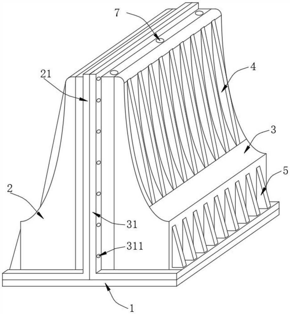
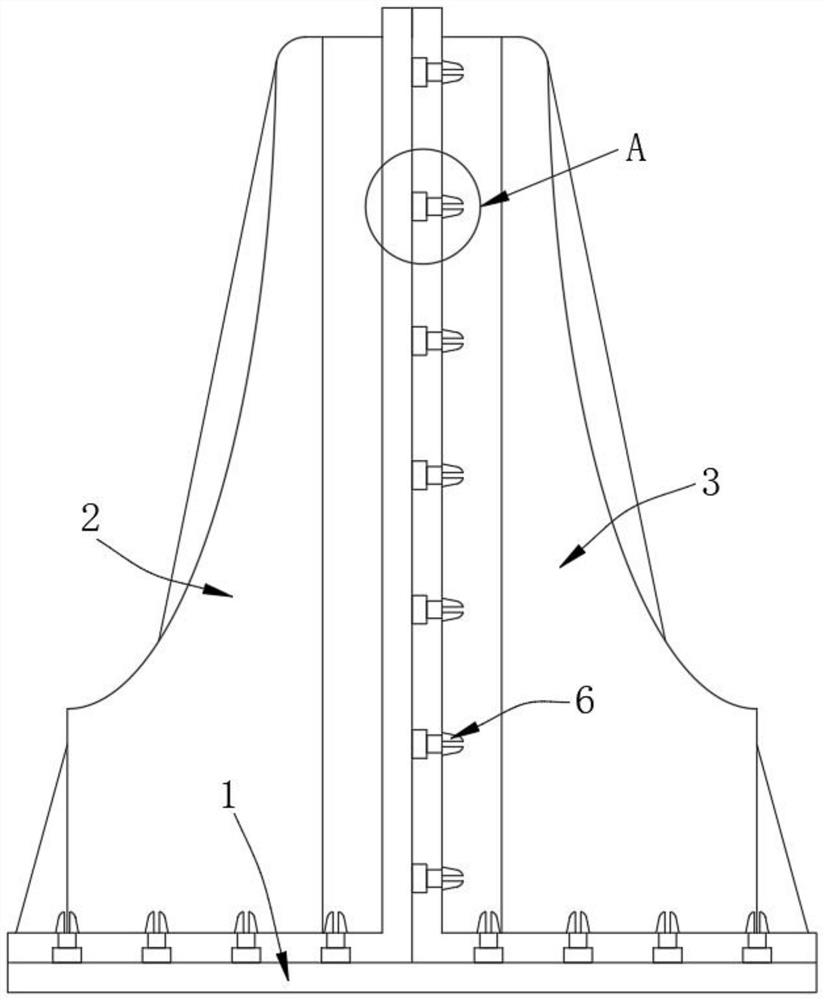
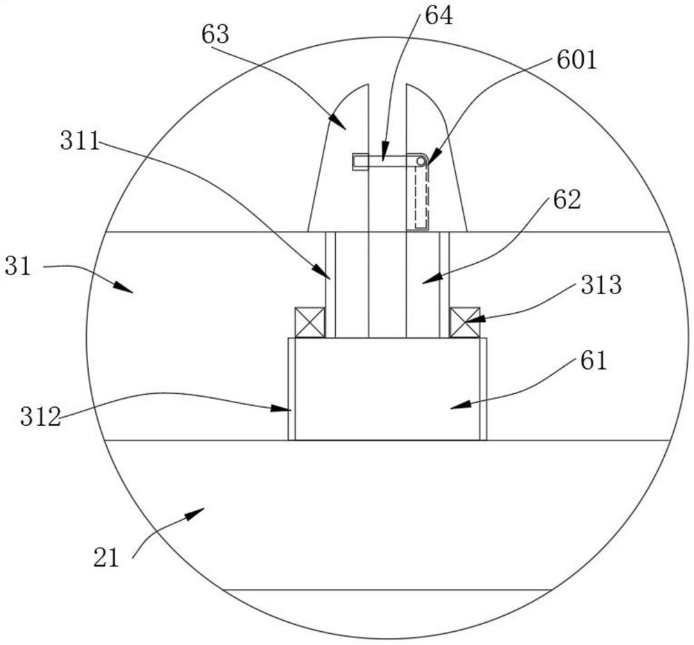
[0026] see Figure 1-3 , the present invention provides the following technical solutions: a combined plastic mold for cast-in-place formwork molding with a locking structure, including a bottom plate 1, a first clamping mold 2 and a second clamping mold 3 that engage with each other, the first clamping mold 2, The second clamping mold 3 is engaged and fixed with each other, and the bottom plate 1 is clamped and installed on the bottom of the first clamping mo...
PUM
Abstract
The invention belongs to the technical field of cement molds, and particularly provides a combined plastic mold for cast-in-situ mold plate shaping and with fastening structure and a processing process thereof. The combined plastic mold comprises a bottom plate, a first buckling mold and a second buckling mold which are buckled with each other; the first buckling mold and the second buckling moldare buckled with each other and fixed; the bottom plate is installed at the bottoms of the first buckling mold and the second buckling mold in a buckling mode; and a first protruding edge plate is arranged at the connecting position between the first buckling mold and the bottom plate and the second buckling mold and protrudes towards the outer side. At the moment a protruding shaft is clamped ina sunken groove hole and is fixed to a magnet in a magnetic attraction mode and the effect of positioning is achieved. Two elastic clamping shafts penetrate through sockets, a limiting buckling platepops towards the outer side and i buckled with the outer side wall of a second protruding edge plate to realize fixation, so the effect of fastening is achieved. At the moment, the bottom plate and the connection between the first buckling mold and the bottom plate are relatively stable and are not prone to unbuckling, and successive fastening and fixation are not required, so more installation and disassembling time can be saved.
Description
technical field [0001] The invention belongs to the technical field of cement moulds, and in particular relates to a combined plastic mold with a locking structure for forming a cast-in-place formwork and a processing technology thereof. Background technique [0002] Cement component mold is also known as concrete component mold, component mold, prefabricated component mold, cement product mold, concrete product mold, common cement component mold types are sink cover mold, railway cover mold, high-speed rail cover mold, road cover mold , manhole cover mold, high-speed cover mold, drainage channel cover mold, drainage ditch cover mold, ditch cover mold, lining cover mold, drainage ditch cover mold, prefabricated component mold, concrete component mold, component mold, cement Component molds, cement product molds, concrete product molds, canal cover molds, water conservancy irrigation molds. [0003] In the existing plastic molds used for pouring cement components, the edges ...
Claims
Application Information
Patent Timeline
Application Date:The date an application was filed.
Publication Date:The date a patent or application was officially published.
First Publication Date:The earliest publication date of a patent with the same application number.
Issue Date:Publication date of the patent grant document.
PCT Entry Date:The Entry date of PCT National Phase.
Estimated Expiry Date:The statutory expiry date of a patent right according to the Patent Law, and it is the longest term of protection that the patent right can achieve without the termination of the patent right due to other reasons(Term extension factor has been taken into account ).
Invalid Date:Actual expiry date is based on effective date or publication date of legal transaction data of invalid patent.