
Servo runner punching mechanism suitable for various punching modes and punching process

A flushing and working technology, applied in the field of semiconductor packaging, can solve the problem of high cost, achieve the effect of improving quality and reducing production cost

Active Publication Date: 2020-09-15
TONGLING FUSHI SANJIA MACHINE
View PDF15 Cites 2 Cited by
  • Summary
  • Abstract
  • Description
  • Claims
  • Application Information

AI Technical Summary

Problems solved by technology

The above three punching methods are different, resulting in different punching runner mechanisms, and the cost of preparing them separately is obviously too high

Method used


Image

  • Servo runner punching mechanism suitable for various punching modes and punching process
  • Servo runner punching mechanism suitable for various punching modes and punching process
  • Servo runner punching mechanism suitable for various punching modes and punching process

Examples


Embodiment 1

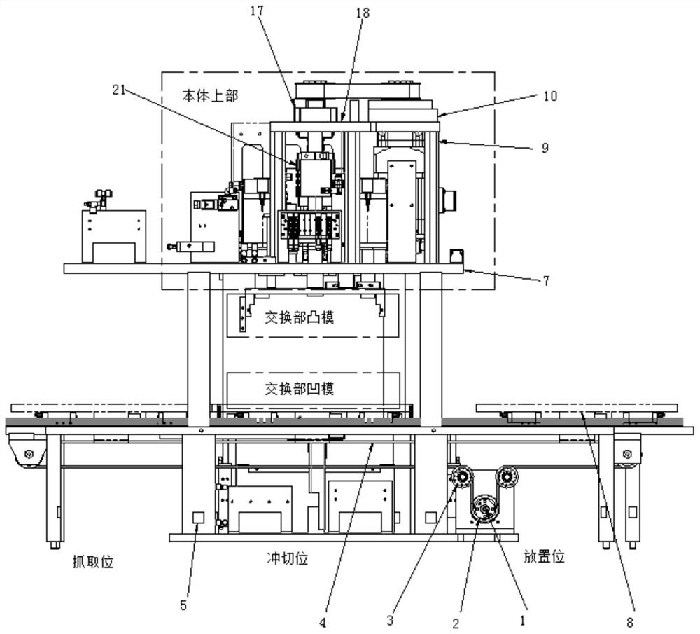
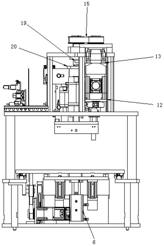
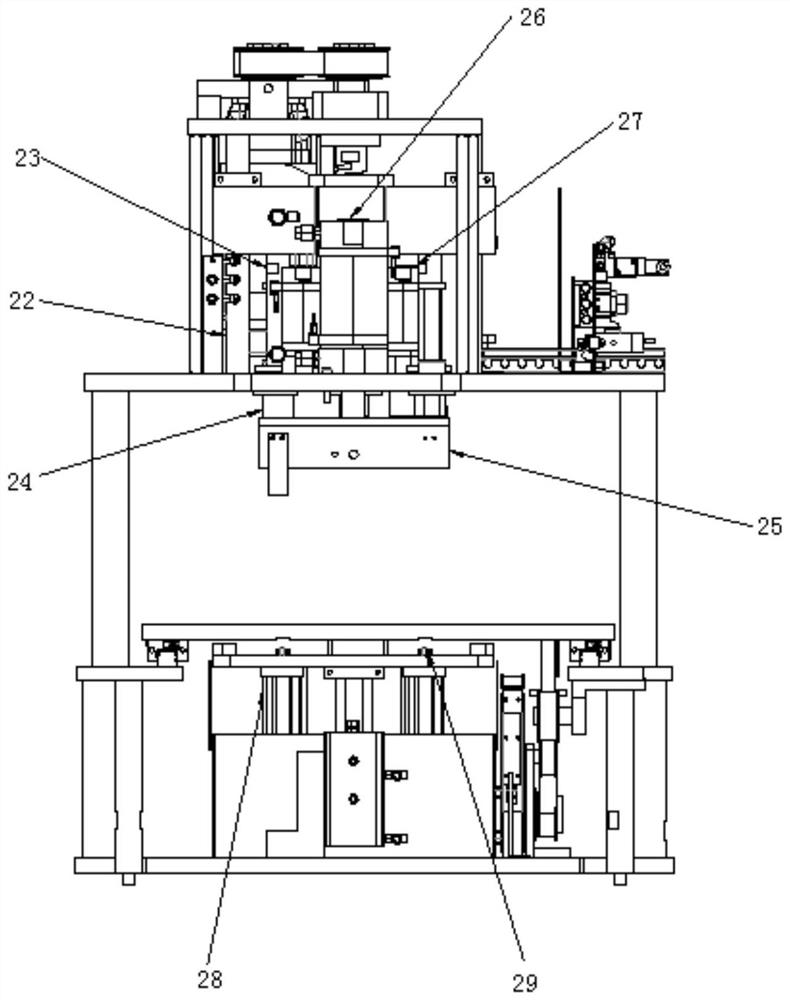
[0041] Embodiment 1, a servo punching device suitable for various punching methods, including a body part and an exchange part, the body part includes a body upper part and a body lower part, and the exchange part includes a punch and a die; the body upper part It includes a servo flushing channel mechanism, a slideway 25 is connected under the servo flushing channel mechanism, and the slideway 25 is connected to the punch. The lower part of the body includes a track, and a moving plate 8 is arranged on the track. The plate 8 is connected with a die, the body below is respectively provided with a cylinder A6 and a cylinder D28, the working end of the cylinder A6 is connected to a support block 59, and the working end of the cylinder D28 is connected with a roller 29; the punch is One of needle punching die, upper folding punch or lower folding punch, and the die is one of needle punching die, upper folding die or lower folding die. There is a servo motor A1 under the body. The...

Embodiment 2

[0046] In Embodiment 2, compared with Embodiment 1, the precise positioning mechanism adopts a structure in which the locking block A and the locking block B cooperate with the fine positioning block. The locking block A and locking block B are located on the die, and the fine positioning block is located on the punch.

Embodiment 3

[0047] In Embodiment 3, compared with Embodiment 2, a handle 31 is fixedly attached to the bottom plate 29 of the needle punching die, and the sensor 35 is connected to the body 30 of the needle punching die through a sensor mounting plate 34 .

[0048] The punching device with this structure is used for punching, because it can take into account the punching methods of needle punching, upper folding, and lower folding. The punching process is to select the type of punch and die according to the work requirements and assemble them. Orbital movement, the lead frame enters the punching work position, the servo runner mechanism starts to work and completes punching, the servo motor A drives the orbital movement, and the lead frame leaves the punching work position; when the needle punching work is performed, the servo runner mechanism drives The needle punching punch is lowered, the servo motor B drives the moving block, and the moving block pushes the moving bottom plate to move ...


PUM


Abstract

The invention discloses a servo punching device suitable for various punching modes and a punching process. The servo punching device is characterized by comprising a body part and an exchange part, wherein the body part comprises an upper body part and a lower body part, and the exchange part comprises a male die and a female die; and the male die is one of a pin punching male die, an upward folding male die and a downward folding male die, and the female die is one of a pin punching female die, an upward folding female die and a downward folding female die. The servo punching device suitablefor various punching modes is simple in structure, stable, efficient and particularly suitable for improving the quality of small-particle products of the SOT series; and according to the punching device with the structure, under the driving of a servo motor, a movable plate bears a lead frame to do reciprocating motion at all working positions, and pin punching, upward folding punching and downward folding punching are achieved through the driving of a servo runner punching mechanism.

Description

technical field [0001] The invention relates to the field of semiconductor packaging, in particular to a servo flushing channel mechanism suitable for various punching methods in an automatic packaging system. Background technique [0002] After the lead frame and epoxy resin complete the plastic sealing process in the mold, the plastic sealed product is put into the die for punching by the unloading robot, and the redundant small gate, runner and Culler are punched for subsequent processing. Prepare for the tendon cutting process. At present, most IC packaging equipment uses cylinders for punching. The structure of the cylinder is affected by the unstable pressure of the air source, and the accuracy of the cylinder is not enough, and the punching force cannot be controlled, resulting in the quality of the punched products cannot be guaranteed. For small particle products of the SOT series, the quality will be affected even more. [0003] At the same time, due to the diffe...

Claims


Application Information

Patent Timeline
IPC IPC(8): B29C45/17B29C45/38B29C45/14H01L21/68H01L21/67B29K63/00
CPCB29C45/1769B29C45/382B29C45/14647H01L21/68H01L21/67092B29K2063/00
Inventor 杨韬汪洋赵仁家汪瑞
Owner TONGLING FUSHI SANJIA MACHINE
Learn More