Printed circuit board collecting and releasing method

A technology of printed circuit boards and rollers, which is applied in the direction of charge manipulation, conveyor objects, object stacking, etc. It can solve the problems of printed circuit board deformation and poor adaptability of suction and holding, and achieve high adaptability and low implementation cost , The effect of simple principle

Active Publication Date: 2020-09-15
SHANTOU ULTRASONIC PRINTED BOARD NO 2 FACTORY
View PDF5 Cites 0 Cited by
  • Summary
  • Abstract
  • Description
  • Claims
  • Application Information

AI Technical Summary

Problems solved by technology

The devices mentioned in the above patents all require a certain area of ​​non-porous area on the board to be sucked for direct suction of the fixed suction cup group. Manual intervention to adjust the position of each suction cup on the fixed suction cup group has typical defects such as poor suction adaptability and easy local deformation of the printed circuit board described in the above background.

Method used


Image

  • Printed circuit board collecting and releasing method
  • Printed circuit board collecting and releasing method
  • Printed circuit board collecting and releasing method

Examples


Embodiment 1

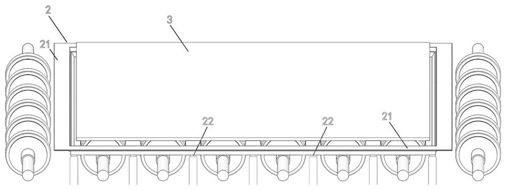
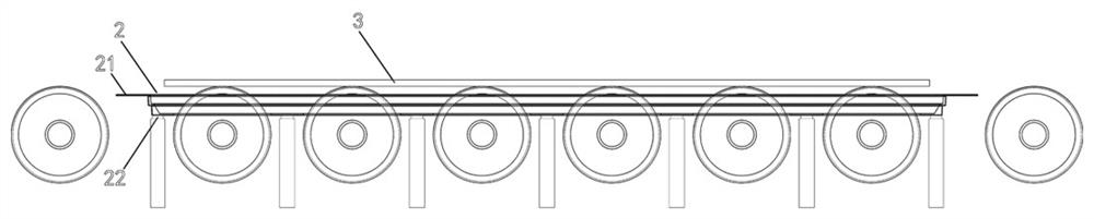
[0048] see Figure 1-3 , in an embodiment of the present invention, a printed circuit board retracting method, using a grasping device to grab and put down the TRAY above the conveying roller, so that the TRAY is combined or separated from the printed circuit board, without directly grabbing and sucking the printed circuit board. Circuit board, to realize the retraction of the non-direct contact printed circuit board.

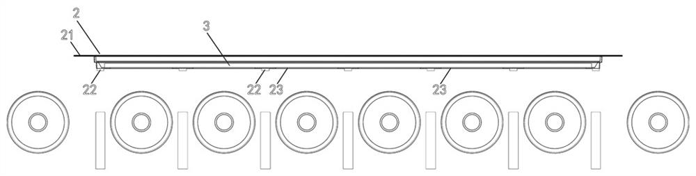
[0049] The bottom hollow 23 of the TRAY, the position of the bottom hollow 23 corresponds to the position of the wheel of the conveying roller one by one, the TRAY can be nested into the conveying roller in this way, and sink completely below the upper surface of the conveying roller .

[0050] The top of the TRAY main body 2 is fixedly provided with a grasping edge 21 that is turned outwards, and the TRAY main body 2 can be grasped through the grasping edge 21, so that the grasping device of the automation equipment can grasp or hold the TRAY. . The grabbing ...

Embodiment 2

[0065] By combining the TRAY with the printed circuit board, first sink the empty TRAY with a hollow bottom under the upper surface of the conveying roller, and when the conveying roller above the TRAY has a printed circuit board, lift the TRAY to combine the TRAY and the printed circuit board, and then transfer this combination to the placement area to achieve the effect of closing the board.

[0066] Please refer to Figure 5 , the action to achieve the closing effect includes the following steps:

[0067] Step 1: Prepare for receiving boards. Place TRAY in the "empty TRAY station". There is no printed circuit board in the TRAY and it is in an unloaded state. Each TRAY is vertically nested with each other to form an unloaded stack.

[0068] Step 2: The grabbing device of the automation equipment moves to the "empty TRAY station".

[0069] Step 3: The grabbing device directly grabs or sucks the plane on the side of the TRAY, and grabs or sucks the empty TRAY from the empty ...


PUM


Abstract

The invention relates to the technical field of printed circuit board manufacturing, and particularly discloses a printed circuit board collecting and releasing method. The bottom of a TRAY is provided with hollowed-out parts, the positions of the hollowed-out parts correspond to positions of wheel blades of conveying idler wheels one to one, and the TRAY can be nested into the conveying idler wheels in this way and completely sunk into the lower parts of the upper surfaces of the conveying idler wheels; and the TRAY is grabbed and put down above the conveying idler wheels through a grabbing device, and thus the TRAY is combined with or separated from a printed circuit board instead of directly grabbing and sucking the printed circuit board. Combination or separation of the TRAY and the printed circuit board is achieved only by grabbing and putting the TRAY, the automatic board collecting and releasing effect without directly grabbing and putting the printed circuit board is achieved,and the defects such as deformation, warping and sinking caused by the fact that existing automatic equipment directly grabs and sucks the printed circuit board to the printed circuit board are thoroughly avoided.

Description

technical field [0001] The invention relates to the technical field of printed circuit board manufacturing, in particular to a method for retracting a printed circuit board. Background technique [0002] In the printed circuit board manufacturing industry, automatic board retractors usually use carriers such as board frames, L frames, and metal trays to realize board retraction by sucking and holding boards. In this way of receiving and releasing boards, separator paper must be used to separate the printed circuit boards to prevent scratches when collecting boards, and separator paper must be taken out when placing boards. The printed circuit board is damaged and scrapped. [0003] In the manufacturing process of high-end printed circuit boards, the WIP is usually loaded with TRAY (material tray) as a carrier, that is, each board is put into a TRAY to achieve the purpose of dust, dirt, anti-scratch and anti-scratch. In the printed circuit board manufacturing process with T...

Claims


Application Information

Patent Timeline
Patent Type & Authority Applications(China)
IPC IPC(8): B65G37/02B65G61/00B65G60/00B65G49/06
CPCB65G37/02B65G49/06B65G60/00B65G61/00B65G2201/0267
Inventor 张学东林旭荣谢勋伟陈兆赓何润宏郭雁深刘宇春
Owner SHANTOU ULTRASONIC PRINTED BOARD NO 2 FACTORY
Why Eureka
Try Eureka