
Double-hard-shell-layer on-site reinforcing and filling structure and method of subgrade in muddy soft soil area

A technology of silt soft soil and hard shell layer, applied in infrastructure engineering, roads, roads, etc., can solve problems such as lack of earthwork for filling roadbed and dredging and replacement, poor roadbed reinforcement effect, and engineering construction hazards. , to achieve the effect of easy promotion and use, fast construction and low cost

Pending Publication Date: 2020-09-15
XIAN UNIV OF SCI & TECH
View PDF0 Cites 0 Cited by
  • Summary
  • Abstract
  • Description
  • Claims
  • Application Information

AI Technical Summary

Problems solved by technology

Silt soft soil is widely distributed in my country's coastal areas and along river basins, which is extremely harmful to engineering construction. Traditional roadbed reinforcement in muddy soft soil areas usually adopts the method of excavating muddy soft soil and replacing it with earthwork. This method The settlement in the later stage of construction is still very large, and the effect of roadbed reinforcement is not good
And for the silty soft soil area where the silty soft soil is widely distributed and the surrounding construction environment is complex, there are often some problems. First, it is inconvenient to excavate the silty soft soil to replace the earthwork; second, to fill the roadbed and Dredging and filling is facing shortage of earthwork
Therefore, there is a lack of an effective method of roadbed reinforcement and filling in silty soft soil areas.

Method used


Image

  • Double-hard-shell-layer on-site reinforcing and filling structure and method of subgrade in muddy soft soil area
  • Double-hard-shell-layer on-site reinforcing and filling structure and method of subgrade in muddy soft soil area

Examples


Embodiment Construction

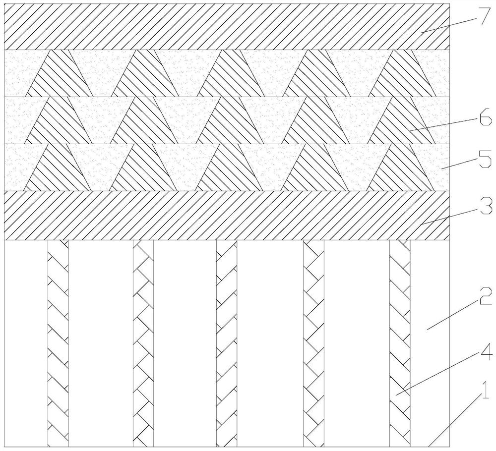
[0032] Such as figure 1 As shown, the in-situ reinforcement and filling structure of the subgrade double hard shell layer in the muddy soft soil area of ​​the present invention includes the first hard shell layer 3 paved on the muddy soft soil layer 2 and a plurality of layers passing through the second hard shell layer respectively. A hard shell layer 3 and a silty soft soil layer 2 are driven to the end-bearing pile 4 on the underlying bedrock 1, and the first hard shell layer 3 is paved with a multi-layer reinforcement layer, and the multi-layer reinforcement layer The top is paved with a second crust layer 7 .

[0033] It should be noted that firstly, the first hard shell layer 3 is paved to provide a working platform for the construction equipment, and then the end-bearing piles 4 are constructed as the load-bearing support foundation, and multi-layer reinforcement layers are paved on the first hard shell layer 3 to form The reinforced pile wall structure and mixed soil ...


PUM


Abstract

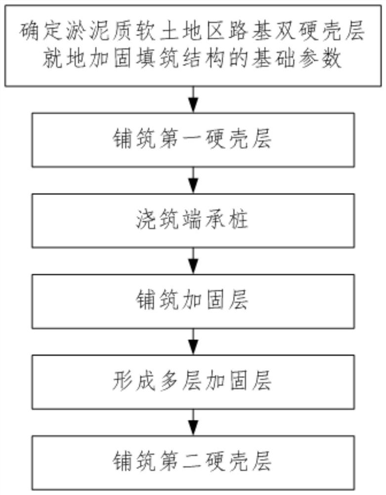
The invention discloses a double-hard-shell-layer in-situ reinforcing and filling structure and method of a subgrade in a muddy soft soil area. The structure comprises a first hard shell layer laid ona muddy soft soil layer and a plurality of end bearing piles which penetrate through the first hard shell layer and the muddy soft soil layer to be hit to underlying bedrock, and a plurality of reinforcing layers and a second hard shell layer are sequentially laid on the first hard shell layer. The method comprises the steps of 1, determining basic parameters of the double-hard-shell-layer in-situ reinforcing and filling structure of the subgrade in the muddy soft soil area; 2, paving the first hard shell layer; 3, pouring the end bearing piles; 4, paving a reinforcing layer; 5, forming a plurality of reinforcing layers; and 6, paving the second hard shell layer. The first hard shell layer is laid, a working platform is provided for construction equipment, then the end bearing piles and the multiple reinforcing layers are constructed, finally, the second hard shell layer is constructed, loads are transmitted to the first hard shell layer through the second hard shell layer and a pilewall structure, the loads are directly transmitted to the underlying bedrock through the end bearing piles, and the whole structure system does not deform or settle.

Description

technical field [0001] The invention belongs to the technical field of in-situ reinforcement of roadbeds in soft soil areas, and in particular relates to an in-situ reinforcement filling structure and method for roadbeds in silty soft soil areas with double hard shell layers. Background technique [0002] The biggest characteristics of the physical and mechanical properties of silty soft soil are high water content, large void ratio, strong permeability, low strength, large deformation, long consolidation time, high compressibility, thixotropy, rheology and strong incompatibility. Uniformity. Silt soft soil is widely distributed in my country's coastal areas and along river basins, which is extremely harmful to engineering construction. Traditional roadbed reinforcement in muddy soft soil areas usually adopts the method of excavating muddy soft soil and replacing it with earthwork. This method The settlement in the later stage of construction is still very large, and the eff...

Claims


Application Information

Patent Timeline
IPC IPC(8): E01C3/00E01C3/04E02D3/00E02D3/12
CPCE01C3/00E01C3/003E01C3/04E02D3/00E02D3/126
Inventor 李晓军王晓华梁居伟马建全刘飞
Owner XIAN UNIV OF SCI & TECH
Learn More