Seabed automatic anchoring device

An anchoring device and anchoring technology, used in anchoring arrangement, transportation and packaging, ship parts, etc., can solve the problem of low drilling efficiency, affecting the drilling force of the anchor, the amount of cutting and the maximum depth, drilling Slow speed and other problems to achieve the effect of improving drilling efficiency and drilling speed

Active Publication Date: 2022-04-08
SOUTHWEST PETROLEUM UNIV
View PDF16 Cites 5 Cited by
  • Summary
  • Abstract
  • Description
  • Claims
  • Application Information

AI Technical Summary

Problems solved by technology

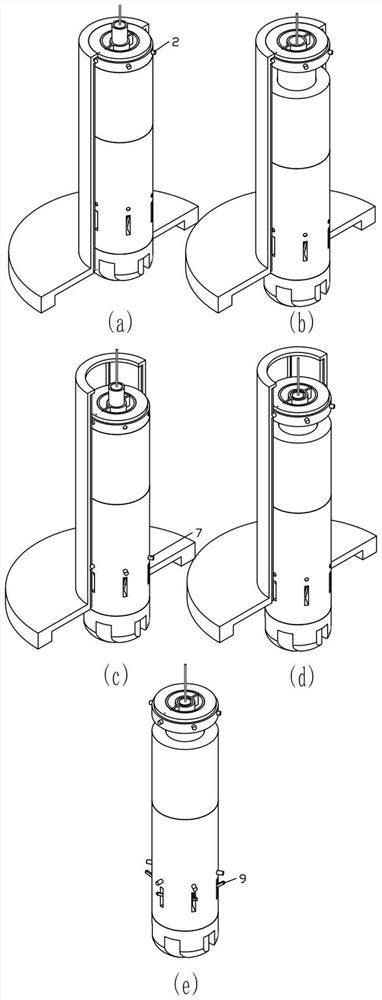
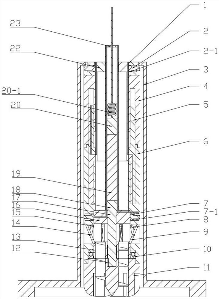
[0009] In order to solve the above-mentioned problems, the present invention provides a seabed automatic anchoring device. The present invention is provided with an external centralizing shell, and the interior of the external centralizing shell is provided with six corresponding slide slots for the anchor block to be anchored. When the external centralizing shell and the internal anchor When the anchor is lowered to the seabed together, under the action of gravity and the pulling force of the cable, the anchoring device can be placed perpendicular to the seabed, which is convenient for subsequent drilling work, and there is no need to install the anchor into the pre-drilled It solves the problem that the traditional anchoring device cannot be placed perpendicular to the seabed when it is lowered to the seabed and needs to be drilled under the pre-drilled pilot hole; the invention has a drilling mechanism , the drilling mechanism has a drill bit with a spiral channel driven by a motor. Driven by the motor, at the same time, the hydraulic pump injects high-pressure oil into the cavity II to drive the lower part of the anchor to move and apply pressure to the drill bit. The drill bit can break the rock. The cuttings are drilled forward, and then drive the entire internal anchor and the cable connected to the internal anchor to be lowered into the seabed rock formation for anchoring, and the drilling pressure is increased through the hydraulic pump, no longer relying only on the anchor itself gravity drilling, which solves the problems of low drilling efficiency and slow drilling speed of traditional anchoring devices; the present invention lays cables inside the anchor, and places the specified length of cables inside the inner tube, During the advancing process of drilling, the cable is released from the inner tube, which solves the problem of the upward pulling force generated by the cable laying method in the traditional anchoring device, which in turn affects the downward drilling force, knife penetration and maximum depth of the anchor. Problem: The present invention is equipped with a connecting rod fixing mechanism. When the anchor drills to a specified depth, the anchor block I in the anchor mechanism I can slide out under the action of the hydraulic pump and squeeze the well wall to generate force. The upper part of the anchor is anchored, and at the same time, the anchor block II of the anchor mechanism II can slide out under the action of the hydraulic pump and squeeze the hole wall to generate force, so that the lower part of the anchor is anchored, and then control The reverse rotation of the motor makes the driving part of the connecting rod move upward in the axial direction, and then drives the connecting rod to move, so that the connecting rod is stretched and squeezed with the well wall to generate force, thereby realizing anchoring and solving the problem of the traditional anchoring device due to the anchoring mechanism. The problem of friction is too low for reliable anchoring

Method used


Image

  • Seabed automatic anchoring device
  • Seabed automatic anchoring device
  • Seabed automatic anchoring device

Examples


Embodiment Construction

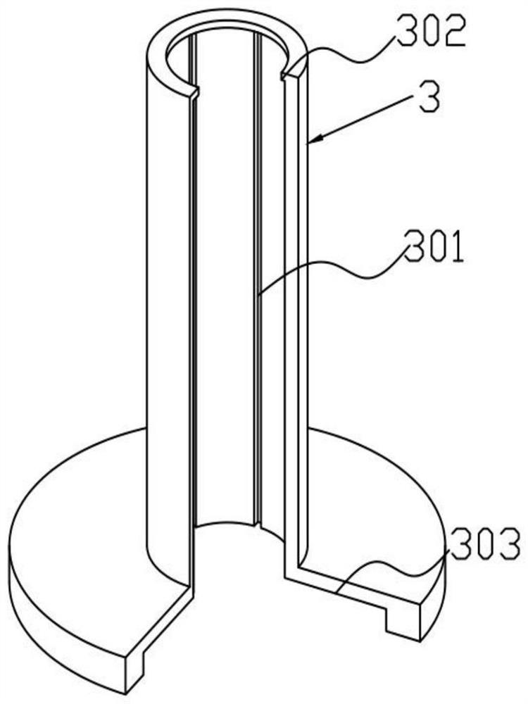
[0035]The invention relates to a seabed automatic anchoring device. The device consists of an external centralizing shell and an internal anchor. The internal anchor includes an upper part and a lower part. The upper part includes the anchoring mechanism I, and the lower part includes the advancing mechanism, anchoring mechanism II, drilling mechanism, and connecting rods. Mechanism; the outer centralizing shell is set outside the inner anchor, and there are six circumferentially evenly distributed slide grooves inside the outer centralizing shell for circumferentially positioning the internal anchor, and the upper part is provided with a limiting shoulder for axial positioning Internal anchor, the lower part is provided with a cavity for the accumulation of cuttings generated at the edge of the drill bit when drilling; the anchor mechanism Ⅰ of the anchor includes anchor sleeve, anchor block Ⅰ, sealing ring Ⅰ, connecting pipe , the sealing ring Ⅰ is installed on the anchor bl...


PUM


Abstract

The invention relates to a seabed automatic anchoring device. The device is composed of an external centralizing shell and an internal anchor, the internal anchor comprises an upper part and a lower part, the upper part and the lower part are connected through a connecting pipe, the upper part comprises an anchoring mechanism I, and the lower part comprises an advancing mechanism, an anchoring mechanism II, a drilling mechanism and a connecting rod fixing mechanism. The anchoring mechanism is mainly composed of an anchoring block and the like. The advancing mechanism mainly comprises a sliding sleeve and the like; the drilling mechanism mainly comprises a drill bit and the like; the connecting rod fixing mechanism is mainly composed of a connecting rod driving piece and the like. The method has the beneficial effects that when drilling and anchoring are needed in the seabed, the internal anchor can start vertical drilling under the condition that no pilot hole exists; the bit pressure can be increased through hydraulic driving, and rapid drilling of the internal anchor is achieved; the mooring rope is arranged in the anchor, so that the drilling acting force of the anchor cannot be influenced; and after drilling to a specified depth, the motor is controlled to rotate reversely, so that the connecting rod is expanded to play an anchoring role, and final anchoring is achieved by matching with the anchoring mechanism I and the anchoring mechanism II.

Description

technical field [0001] The invention relates to the field of marine equipment, in particular to a seabed automatic anchoring device used for floating equipment in the marine industry. Background technique [0002] In modern ocean development activities, the scale and output value of offshore oil extraction, natural gas development, wave energy development, and offshore wind power generation are increasing, and the application of offshore floating equipment is becoming more and more extensive. Therefore, a reliable seabed anchor is required. Device to solve the anchoring problem of offshore floating equipment and platforms. [0003] During the seabed anchoring operation, the anchor must be placed in the borehole that has been drilled by other equipment before starting to work. If there is no pre-drilled borehole, the anchor may not be able to drill perpendicular to the seabed , causing problems such as unreliable anchoring and easy anchoring. At present, there are seabed an...

Claims


Application Information

Patent Timeline
Patent Type & Authority Applications(China)
IPC IPC(8): B63B21/50
Inventor 唐洋肖枭师婷张雨翔张金梁康传哲粟籽华赵吉锐唐鑫王国荣何玉发王金忠赵金海
Owner SOUTHWEST PETROLEUM UNIV
Why Eureka
Try Eureka