An axial flow pump impeller and axial flow pump

An axial-flow pump and impeller technology, which is applied to axial-flow pumps, pumps, and components of pumping devices for elastic fluids, etc., can solve the problems of reduced hydraulic performance, complex structure, and high construction costs, and can increase the axial speed. , the effect of reducing the impact probability, head and efficiency satisfaction

Active Publication Date: 2021-09-17
JIANGSU UNIV ZHENJIANG RES INST OF FLUID ENG EQUIP TECH +1
View PDF9 Cites 0 Cited by
  • Summary
  • Abstract
  • Description
  • Claims
  • Application Information

AI Technical Summary

Problems solved by technology

However, compared with the traditional axial flow pump, the structure of the device is complex, the construction cost is high, and the transmission efficiency affects the overall operating efficiency and stability of the pump system. The leakage screen increases the flow resistance and reduces the hydraulic performance. The mesh size of the leakage screen also determined that smaller fish cannot be protected

Method used


Image

  • An axial flow pump impeller and axial flow pump
  • An axial flow pump impeller and axial flow pump
  • An axial flow pump impeller and axial flow pump

Examples


Embodiment

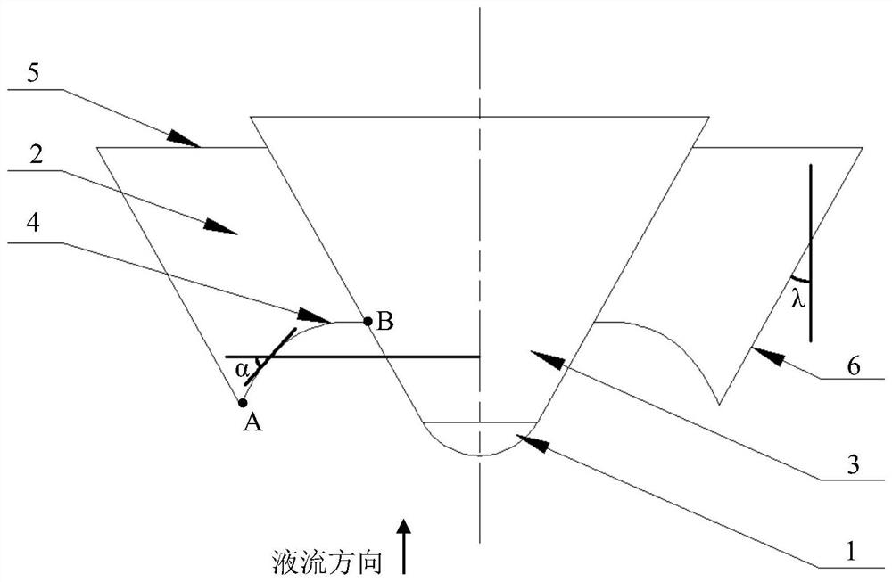
[0029] see figure 1 , figure 1 It is an axial view of an axial flow pump impeller provided by the embodiment of the present invention. The axial flow pump impeller is mostly used in large pumping stations, and its ND value is generally within 350, where N is the rotational speed (rpm), and D is the outer surface of the impeller. diameter (m). Such as figure 1 As shown, the impeller of the axial flow pump mainly includes a diversion cap 1, an impeller blade 2 and an impeller hub 3;

[0030] The diversion cap 1 is a partial structure of a sphere, the impeller hub 3 is a circular platform structure, the diversion cap 1 is connected to the bottom of the impeller hub 3, and the bus line of the impeller hub 3 is tangent to the outline of the partial structure of the sphere;

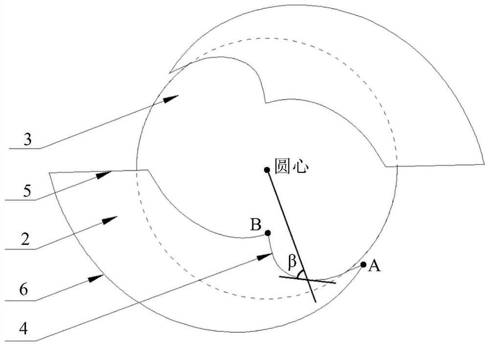
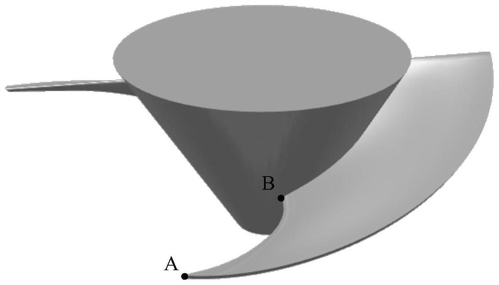
[0031] The impeller blade 2 is fixed on the impeller hub 3, and the impeller blade 2 includes a blade leading edge 4, a blade trailing edge 5 and a blade rim 6; the radius of the blade rim 6 gradually increa...


PUM


Abstract

The invention provides an impeller of an axial flow pump and an axial flow pump. The impeller of the axial flow pump includes a diversion cap 1, impeller blades 2 and an impeller hub 3; The cap 1 is connected to the bottom of the impeller hub 3, and the generatrix of the impeller hub 3 is tangent to the outline of the local structure of the sphere; the impeller blade 2 is fixed on the impeller hub 3, and the impeller blade 2 includes a blade leading edge 4, a blade trailing edge 5 and a blade The radius of the rim 5 and the blade rim 6 gradually increases along the liquid flow direction, and the surface of the blade rim 6 is the side of the circular platform, and the generatrix of the side of the circular platform where the blade rim 6 is located is parallel to the generatrix of the impeller hub 3 . The present invention adopts the impeller with gradually changing outer diameter, and the outer diameter at the inlet of the impeller is smaller, so as to increase the liquid flow and the axial velocity of the organism passing through the pump, thereby reducing the collision probability between the organism and the leading edge 4 of the blade. In addition, the diameter of the impeller outlet is kept relatively large, which can ensure that the pump head and efficiency meet the requirements of the pumping station.

Description

technical field [0001] The invention relates to the technical field of fluid machinery, in particular to an axial flow pump impeller and an axial flow pump. Background technique [0002] Axial flow pumps have the characteristics of large flow, low head, and high efficiency. Due to their small size and low construction cost, they are widely used in pumping station construction projects such as water diversion projects, flood control and drainage, and agricultural irrigation in my country. [0003] However, when biological resources (such as fish, shrimp, etc.) in rivers and lakes pass through the axial flow pump passively with the liquid flow, a large amount of biological damage and death often occur. On the one hand, the migration and migration of fish are hindered, and their population numbers and even the diversity of fish species are affected. For example, European eels and sticklebacks must migrate in salt water of oceans and fresh water of lakes to complete their life c...

Claims


Application Information

Patent Timeline
Patent Type & Authority Patents(China)
IPC IPC(8): F04D29/18F04D3/00
CPCF04D3/00F04D3/005F04D29/181
Inventor 潘强张德胜施卫东赵睿杰黄俊高雄发
Owner JIANGSU UNIV ZHENJIANG RES INST OF FLUID ENG EQUIP TECH
Why Eureka
Try Eureka