
Optical fiber drawing bad section automatic detection device and method

An automatic detection device and a technology for broken wire segments, applied in the field of optical fiber manufacturing, can solve the problems of unable to pull optical fiber detection, heavy workload, scrapped qualified optical fibers, etc., and achieve the effect of reducing subsequent defective products and saving calculations

Inactive Publication Date: 2020-09-15
JIANGSU ETERN OPTICAL FIBER TECH CO LTD
View PDF6 Cites 1 Cited by
  • Summary
  • Abstract
  • Description
  • Claims
  • Application Information

AI Technical Summary

Problems solved by technology

[0003] The existing technology needs to report the number of kilometers of unqualified optical fibers according to different wire diameter meters, then remove them by manual calculation, and then enter them into the database. The workload is heavy and cumbersome, and the drawn optical fibers cannot be detected in time.
Omissions and miscalculations are also prone to occur when calculating the length of optical fibers in the existing technology, which makes qualified optical fibers scrapped, increases costs, and causes unqualified optical fibers to flow out and be put into use, reducing the overall service life and performance of optical fibers

Method used


Image

  • Optical fiber drawing bad section automatic detection device and method
  • Optical fiber drawing bad section automatic detection device and method

Examples


Embodiment Construction

[0023] It should be noted that, in the case of no conflict, the embodiments in the present application and the features in the embodiments can be combined with each other.

[0024] In the description of the present application, it should be understood that the terms "center", "longitudinal", "transverse", "upper", "lower", "front", "rear", "left", "right", " The orientation or positional relationship indicated by "vertical", "horizontal", "top", "bottom", "inner", "outer", etc. is based on the orientation or positional relationship shown in the drawings, and is only for the convenience of describing the present application and Simplified descriptions do not indicate or imply that the device or element referred to must have a specific orientation, be constructed and operate in a specific orientation, and thus should not be construed as limiting the scope of protection of the present application. In addition, the terms "first", "second", etc. are used for descriptive purposes on...


PUM


Abstract

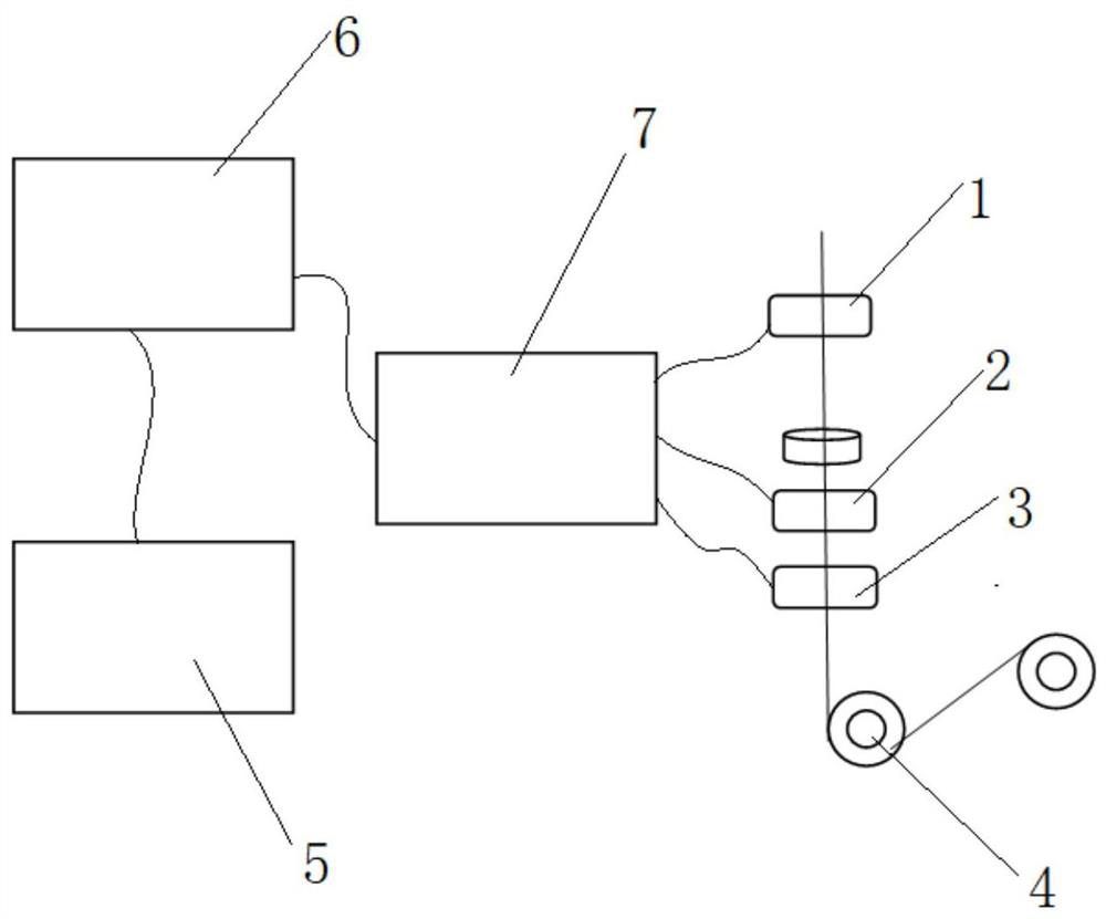
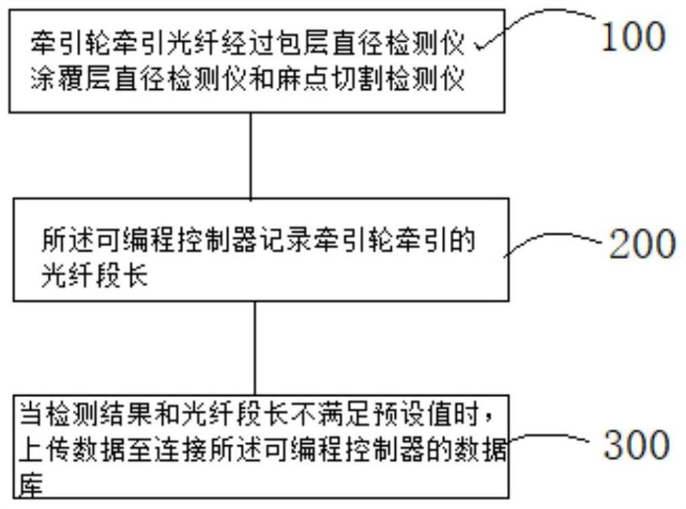
The invention relates to an optical fiber drawing bad section automatic detection device and method. The device comprises a traction assembly, a detection assembly, a storage operation assembly and adisplay assembly; the detection assembly comprises a cladding diameter detector, a coating layer diameter detector and a pocking mark cutting detector; the traction assembly comprises a traction wheel; the traction wheel pulls an optical fiber to pass through the detection assembly and detect the optical fiber, the storage operation assembly comprises a database and a programmable logic controller, the programmable logic controller is connected with the database and the detection assembly, and the programmable logic controller processes a detection result of the detection assembly and uploadsthe detection result to the database. According to the invention, the positions of original unqualified optical fibers are stored to one position, the programmable controller can simultaneously process and calculate various unqualified optical fibers, and removes and automatically uploads the unqualified optical fibers to the database according to set unqualified optical fiber indexes and qualified optical fibers which do not meet the minimum segment length, thereby realizing automatic control.

Description

technical field [0001] The application belongs to the field of optical fiber production and manufacturing, and in particular relates to an automatic detection device and detection method for an optical fiber drawing broken section. Background technique [0002] In the process of optical fiber production, there will be some unqualified optical fibers such as cladding diameter, coating diameter, and pit cutting that do not meet the requirements. In order to ensure the performance of optical fibers, it is necessary to detect and remove these unqualified optical fibers. Accurate detection and removal of unqualified optical fibers is a key step in producing optical fibers and reducing the defective rate. [0003] The existing technology needs to report the kilometers of unqualified optical fibers according to different wire diameter meters, then remove them by manual calculation, and then enter them into the database. The workload is heavy and cumbersome, and the drawn optical f...

Claims


Application Information

Patent Timeline
Patent Type & Authority Applications(China)
IPC IPC(8): G01B21/10G01B21/18G01B21/02B07C5/36
CPCB07C5/361G01B21/02G01B21/10G01B21/18
Inventor 邓纯样王新超赵晨明马云鹏张云飞徐阳
Owner JIANGSU ETERN OPTICAL FIBER TECH CO LTD
Learn More