A Compensation Method for Spatial Positioning Error Based on Siemens System

A technology of spatial positioning and error compensation, applied in the field of CNC machine tools, can solve the problems of inability to cover the spatial positioning accuracy error term of machine tools and high compensation accuracy, and achieve the effect of improving spatial positioning accuracy, accurate compensation accuracy and processing accuracy.

Active Publication Date: 2021-08-03
CHENGDU AIRCRAFT INDUSTRY GROUP
View PDF8 Cites 0 Cited by
  • Summary
  • Abstract
  • Description
  • Claims
  • Application Information

AI Technical Summary

Problems solved by technology

[0006] In order to solve the above technical problems, the present invention proposes a space positioning error compensation method based on the Siemens system, which can effectively solve the problem that all error items that affect the space positioning accuracy of the machine tool cannot be covered, and the compensation accuracy is higher

Method used


Image

  • A Compensation Method for Spatial Positioning Error Based on Siemens System
  • A Compensation Method for Spatial Positioning Error Based on Siemens System
  • A Compensation Method for Spatial Positioning Error Based on Siemens System

Examples


Embodiment 1

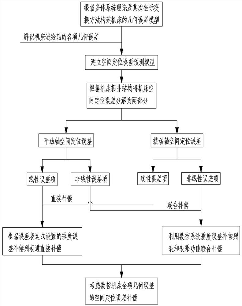
[0049] As the basic implementation mode of the present invention, the present invention includes a kind of spatial positioning error compensation method based on Siemens system, comprising the following steps:

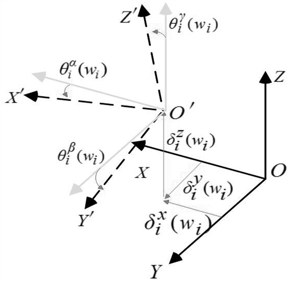
[0050] a. Construct the mapping relationship between the geometric error of each feed axis of the five-axis CNC machine tool and the tool space positioning error, establish the geometric error model of the five-axis CNC machine tool, and provide a mathematical basis for the compensation of space positioning errors;

[0051] b. Identify the various geometric errors of the feed axis of the machine tool, bring them into the geometric error model established in step a, establish a spatial positioning error prediction model, and predict the spatial positioning error of the five-axis CNC machine tool, which is the spatial positioning error Compensation provides direct guidance;

[0052] c. Combining the spatial positioning error prediction model and the sag error compensation ...

Embodiment 2

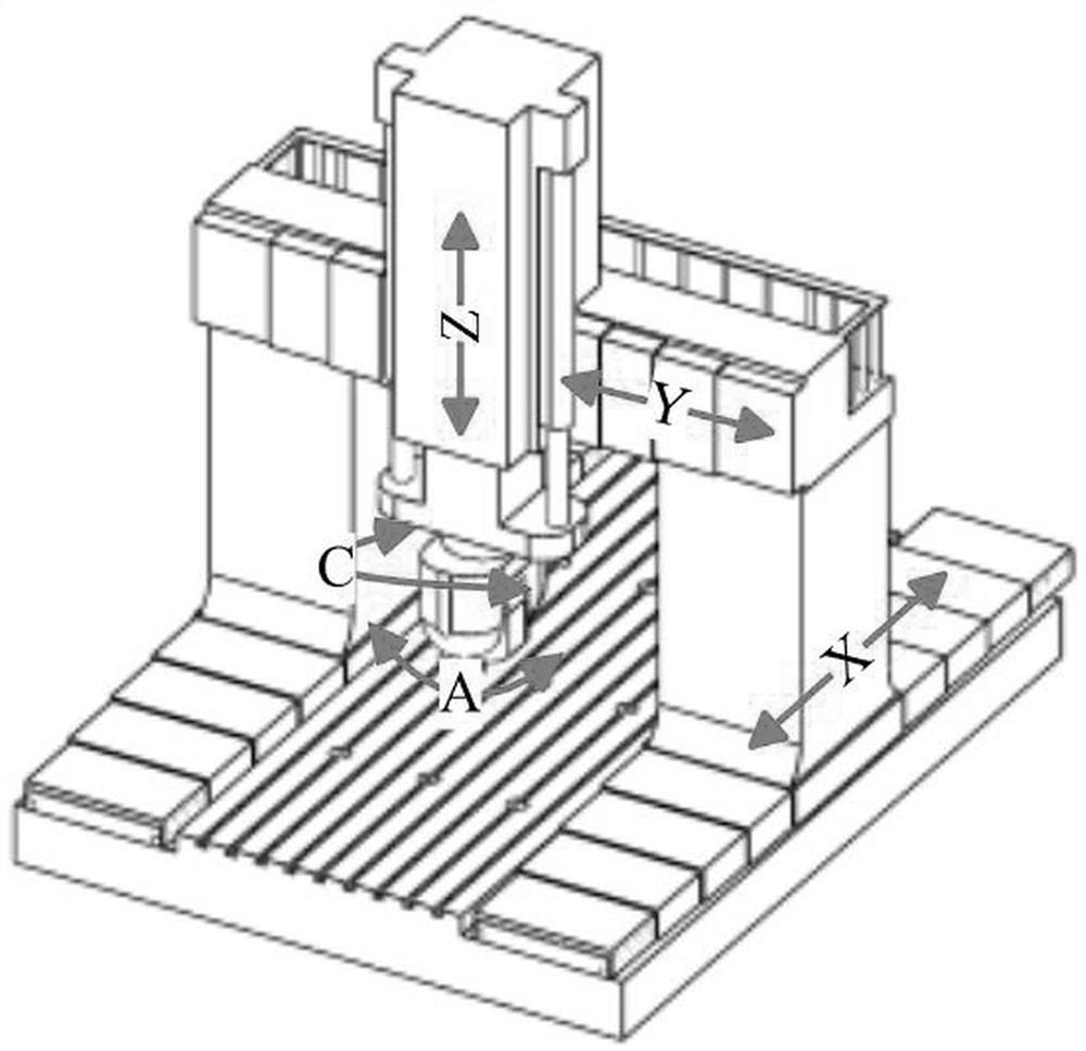
[0054] The five-axis CNC machine tool is composed of three translational axes and two swinging axes. According to the combination sequence of the translational axes and the swinging axes, five-axis machine tools with different topological structures will be produced. These five-axis machine tools can realize complex five-degree-of-freedom machining. Among them, the mobile gantry five-axis CNC machine tool has a large span and a long processing stroke, which is most suitable for processing large and complex structural parts. It has a large working space and high processing accuracy requirements. There is a strong demand for positioning error compensation. As the best implementation mode of the present invention, the present invention is aimed at the compensation of space positioning error of the mobile gantry type five-axis machine tool, which specifically includes: geometric error modeling of the five-axis CNC machine tool, prediction of the space positioning error of the five-...


PUM


Abstract

The present invention relates to the technical field of numerically controlled machine tools, in particular to a method for compensating space positioning errors based on the Siemens system, including three modules: geometric error modeling, space positioning error prediction, and space positioning error compensation. Establish a geometric error model for the mapping relationship between the axis geometric error and the tool space positioning error; identify the various geometric errors of the feed axis of the machine tool, bring them into the geometric error model, and establish a spatial positioning error prediction model; combine the spatial positioning error prediction model with Siemens The sag error compensation interface of the CNC system compensates the spatial positioning error of the five-axis CNC machine tool. The method can effectively solve the problem that all error items affecting the spatial positioning accuracy of the machine tool cannot be covered, and the compensation accuracy is higher.

Description

technical field [0001] The invention relates to the technical field of numerical control machine tools, in particular to a method for compensating space positioning errors based on a Siemens system. Background technique [0002] Five-axis CNC machine tools are widely used in the processing of complex parts in aviation, aerospace, automobile and other manufacturing fields. With the continuous improvement of people's demand for product performance, the requirements for the precision of five-axis linkage machining of corresponding products are also gradually rising. Especially in the field of aircraft manufacturing, the high stealth, high maneuverability, and high load performance requirements of the new generation of aircraft make the structural parts more large, complex, and compact, which poses a great challenge to the machining accuracy of five-axis CNC machine tools . In addition, large and ultra-large five-axis CNC machine tools are widely used in the field of aviation ...

Claims


Application Information

Patent Timeline
Patent Type & Authority Patents(China)
IPC IPC(8): G05B19/404
CPCG05B19/404G05B2219/35408
Inventor 李杰李颖李庆郭瑞华李连玉张云
Owner CHENGDU AIRCRAFT INDUSTRY GROUP
Why Eureka
Try Eureka