Method for improving precision of carbonatite dynamic and static Young modulus conversion model

A technology of static Young's modulus and Young's modulus, which can be used in measuring devices, geographic modeling, geophysical measurement, etc., and can solve the problems of loss of engineering guidance, low accuracy, and lack of dynamic and static Young's modulus conversion Model accuracy and other issues, to achieve the effect of ensuring feasibility and convenience, and good correction effect

Active Publication Date: 2020-09-15
CHINA UNIV OF PETROLEUM (EAST CHINA)
3 Cites 0 Cited by

AI-Extracted Technical Summary

Problems solved by technology

For rock formations with good physical properties and low anisotropy, a dynamic and static Young's modulus conversion model with high accuracy can be fitted through experiments. For rock formations with strong anisotropy and complex pore structure, the dynamic and static Young's modulus conversion model obtained through indoor experiment fitting is usually not very accurate, and has lost its guiding significance for actual engineering
[0010] Carbonatite reservoirs are c...

Method used

The static Young's modulus correction result of 16 carbonatite rock samples of the present embodiment is as shown in table 1, in order to verify that the inventive method is conducive to improving the carbonatite dynamic and static Young's modulus conversion model precision, calculates the present embodiment The variance between the fitted static Young's modulus of 16 carbonatite rock cores and the experimental static Young's modulus, the calculation results are as shown in table 1, by utilizing the method of the present invention to correc...

Abstract

The invention discloses a method for improving the precision of a carbonatite dynamic and static Young modulus conversion model, and particularly relates to the field of carbonatite reservoir logging.The method comprises the following steps: 1, establishing a dynamic and static Young modulus conversion model according to rock physical experiment data; 2, establishing a regression model M1 of an experimental dynamic and static Young modulus difference value S2--a static Young modulus fitting value and an experimental value difference value S1 by utilizing the dynamic and static Young modulus conversion model and rock physical experimental data; 3, establishing a regression model M2 of the experimental dynamic and static Young modulus difference S2 -- porosity according to the rock physicalexperimental data; 4, establishing a correction value model M3; and 5, calculating the fitting static Young modulus of the point to be measured, and correcting by using the regression model M1, the regression model M2 and the correction value model M3 to obtain the corrected static Young modulus. According to the method, the precision of the carbonatite dynamic and static Young modulus conversionmodel is improved, and well logging evaluation and oil field development of the carbonatite reservoir are facilitated.

Application Domain

Technology Topic

Image

  • Method for improving precision of carbonatite dynamic and static Young modulus conversion model
  • Method for improving precision of carbonatite dynamic and static Young modulus conversion model
  • Method for improving precision of carbonatite dynamic and static Young modulus conversion model

Examples

  • Experimental program(1)

Example Embodiment

[0033] The specific embodiments of the present invention will be further described below in conjunction with the accompanying drawings and an example well in a certain carbonate block:
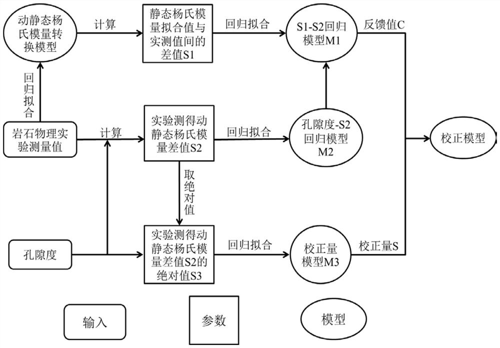
[0034] figure 1 Shown is a flow chart of a method for improving the accuracy of the dynamic and static Young's modulus conversion model of carbonate rock, which specifically includes the following steps:
[0035] Step 1, establish a dynamic and static Young's modulus conversion model;
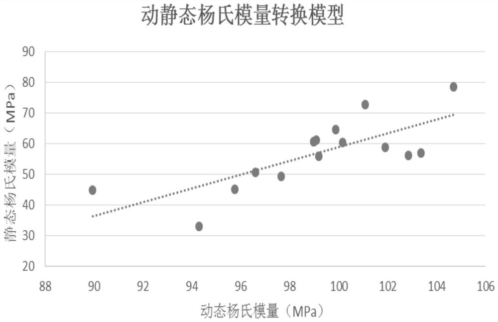
[0036] In this example, 16 standard-sized cores from a sample well in a certain carbonate block are used for petrophysical experiments, and the core size is 250 mm. The porosity, experimental dynamic Young's modulus and The experimental static Young's modulus, the measurement results are shown in Table 1, the regression analysis software was used to linearly fit the experimental dynamic Young's modulus and the experimental static Young's modulus of the carbonate rock sample, and the dynamic and static Young's modulus was established. Quantitative transformation models, such as figure 2 As shown, the dynamic and static Young's modulus conversion model is:
[0037] E s = 2.2366E d -164.72 (3)
[0038] In the formula, E d represents the experimental dynamic Young's modulus, in MPa; E S Indicates the experimental static Young's modulus, in MPa;
[0039] Step 2, establish the experimental dynamic and static Young's modulus difference S 2 ——The difference between the fitted value of the static Young's modulus and the experimental value S 1 The regression model M1;
[0040] The experimental dynamic Young's modulus of each carbonate rock sample measured by petrophysical experiments was substituted into the established dynamic and static Young's modulus conversion model, and the fitted static Young's modulus of each carbonate rock sample was calculated. The fitted static Young's modulus of the rock sample is subtracted from the experimental static Young's modulus to obtain the difference S between the fitted static Young's modulus and the experimental static Young's modulus. 1 , and then subtract the experimental static Young's modulus from the experimental dynamic Young's modulus of each carbonate rock sample to obtain the difference S between the experimental dynamic Young's modulus and the experimental static Young's modulus 2 , the calculation results are shown in Table 1;
[0041] Using regression analysis software to analyze the difference S 1 and difference S 2 Perform linear fitting to establish a regression model M1, such as image 3 As shown, the regression model M1 is:
[0042] S 1 =0.7134S 2-30.144 (4)
[0043] In the formula, S 2 Represents the difference between the experimental dynamic and static Young's modulus, in MPa; S 1 Represents the difference between the fitted static Young's modulus and the experimental static Young's modulus, in MPa;
[0044] Step 3, establish the experimental dynamic and static Young's modulus difference S 2 - regression model M2 of porosity;
[0045] Porosity measured from petrophysical experiments and the difference S between the experimental dynamic Young's modulus and the experimental static Young's modulus 2 , using regression analysis software to measure the difference S 2 Perform linear fitting with porosity to establish a regression model M2, such as Figure 4 As shown, the regression model M2 is:
[0046] S 2 =15.044φ+62.525 (5)
[0047] In the formula, φ represents the porosity, and the unit is %; S 2 Indicates the difference between the experimental dynamic and static Young's modulus, in MPa;
[0048] Step 4, establish a correction amount model M3;
[0049] The difference between the fitted static Young's modulus and the experimental static Young's modulus S 1 Take the absolute value to get S 3 , the calculation results are shown in Table 1. Using regression analysis software, the porosity and absolute value S measured by petrophysical experiments 3 Perform linear fitting to establish a correction model M3, such as Figure 5 As shown, the correction amount model M3 is:
[0050] S 3 =-0.1187φ+6.1138 (6)
[0051] In the formula, φ represents the porosity, and the unit is %; S 3 Represents the difference between the fitted static Young's modulus and the experimental static Young's modulus S 1 The absolute value of , the unit is MPa;
[0052] Step 5: Convert the experimental dynamic Young's modulus of the point to be measured into the fitted static Young's modulus through the dynamic and static Young's modulus conversion model. According to the porosity of each carbonate rock sample, use the regression model M1, regression model M2 and correction model M3, correct the fitted static Young's modulus of each carbonate rock sample to obtain the corrected static Young's modulus;
[0053] The experimental dynamic Young's modulus measured by 16 standard size carbonate rock cores in the present embodiment is substituted into the dynamic and static Young's modulus conversion model, and the fitted static Young's modulus of each carbonate rock core is calculated;
[0054] By substituting the porosity of each carbonate core into the regression model M2, the experimental dynamic and static Young's modulus difference S is calculated. 2 The feedback value C 1; then the feedback value C 1 Substitute into the regression model M1, and calculate the difference S between the fitted value of the static Young's modulus and the experimental value. 1 Finally, the porosity of each carbonatite core is substituted into the correction value model M3, and the fitted static Young's modulus correction value S of each carbonatite core is calculated, the feedback value C and correction value S of this embodiment are obtained. The calculation results are shown in Table 1;
[0055] If the feedback value of the carbonatite core is C>0, subtract the correction amount S from the fitted static Young's modulus of the carbonate core to obtain the corrected static Young's modulus; if the feedback value of the carbonatite core is C<0 , the fitted static Young's modulus of the carbonate core is added to the correction amount S to obtain the corrected static Young's modulus.
[0056] Table 1 shows the static Young's modulus correction results of the 16 carbonatite samples in this example. The variance between the fitted static Young's modulus of carbonatite cores and the experimental static Young's modulus, the calculation results are shown in Table 1. After 16 carbonatite cores in this example are corrected by the method of the present invention, 16 The variance between the fitted static Young's modulus of the block carbonatite core and the experimental static Young's modulus is significantly reduced, and the goodness of fit is improved from the uncorrected 0.5678 to 0.893. It can be seen that the method of the present invention effectively improves the The accuracy of the dynamic and static Young's modulus conversion model of carbonate rock is obtained, which is beneficial to carbonate reservoir evaluation and oilfield development.
[0057] Of course, the above description is not intended to limit the present invention, and the present invention is not limited to the above examples. Changes, modifications, additions or substitutions made by those skilled in the art within the essential scope of the present invention should also belong to the present invention. the scope of protection of the invention.
[0058] Table 1. Summary of dynamic and static Young's modulus conversion correction parameters
[0059]

PUM

no PUM

Description & Claims & Application Information

We can also present the details of the Description, Claims and Application information to help users get a comprehensive understanding of the technical details of the patent, such as background art, summary of invention, brief description of drawings, description of embodiments, and other original content. On the other hand, users can also determine the specific scope of protection of the technology through the list of claims; as well as understand the changes in the life cycle of the technology with the presentation of the patent timeline. Login to view more.

Similar technology patents

Construction method for deviation rectification of open caisson

PendingCN114319408AGood correction effectCorrection accuracyCaissonsSoil scienceWater area
Owner:CHINA RAILWAY MAJOR BRIDGE ENG GRP CO LTD +1

Method for eliminating vignetting phenomenon in surgical microimaging

PendingCN111260573AGood correction effectEliminate vignettingImage enhancementOphthalmologyMicrosurgery
Owner:ZHEJIANG FUTURE TECH INST JIAXING

Classification and recommendation of technical efficacy words

Why Eureka
Try Eureka