
Combined multi-stage rotary paint powder sanding device

A combination and coating technology, applied in the field of coatings, can solve the problems of limiting the grinding efficiency of the sand mill, the low grinding efficiency of the sand mill, and the poor heat dissipation effect of the sand mill, so as to increase the movement effect, improve the crushing effect, increase the The effect of efficiency and quality

Active Publication Date: 2020-09-18
山东鸿粤新材料有限公司
View PDF4 Cites 1 Cited by
  • Summary
  • Abstract
  • Description
  • Claims
  • Application Information

AI Technical Summary

Problems solved by technology

[0003] In the coating powder processing process, it is usually necessary to use a sand mill to grind the coating, and the existing sand mill is equipped with media for grinding such as zirconium beads, glass beads, etc. in a closed cylinder. The dispersing disc on the top moves the medium in the cylinder to make the media move relative to each other, allowing the materials to be ground to pass through the media to achieve the effect of crushing. The movement of the media is caused only by the distributing disc on the rotating shaft. The efficiency and collision effect are poor, which leads to the low grinding efficiency and unsatisfactory grinding effect of the existing sand mill, and the poor heat dissipation effect of the existing sand mill further limits the grinding efficiency of the sand mill

Method used


Image

  • Combined multi-stage rotary paint powder sanding device
  • Combined multi-stage rotary paint powder sanding device
  • Combined multi-stage rotary paint powder sanding device

Examples


Embodiment Construction

[0027] The following will clearly and completely describe the technical solutions in the embodiments of the present invention with reference to the accompanying drawings in the embodiments of the present invention. Obviously, the described embodiments are only some, not all, embodiments of the present invention. Based on the embodiments of the present invention, all other embodiments obtained by persons of ordinary skill in the art without making creative efforts belong to the protection scope of the present invention.

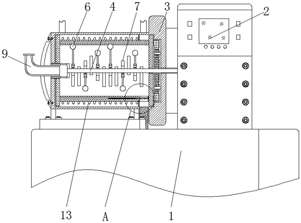
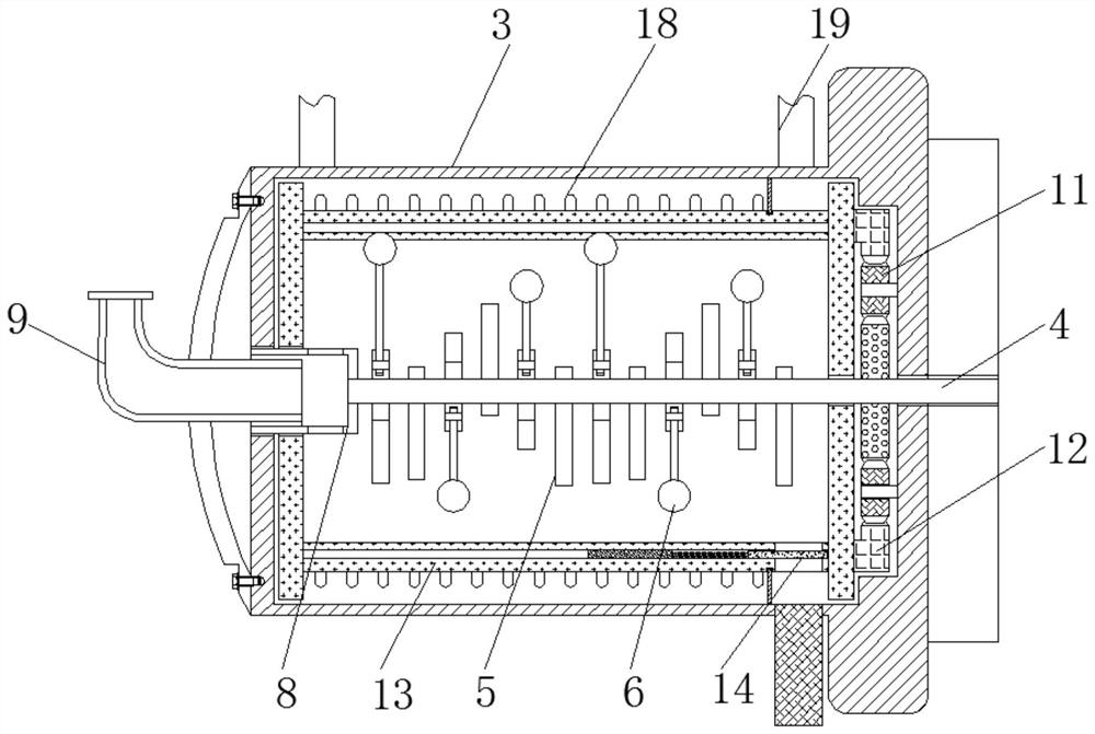
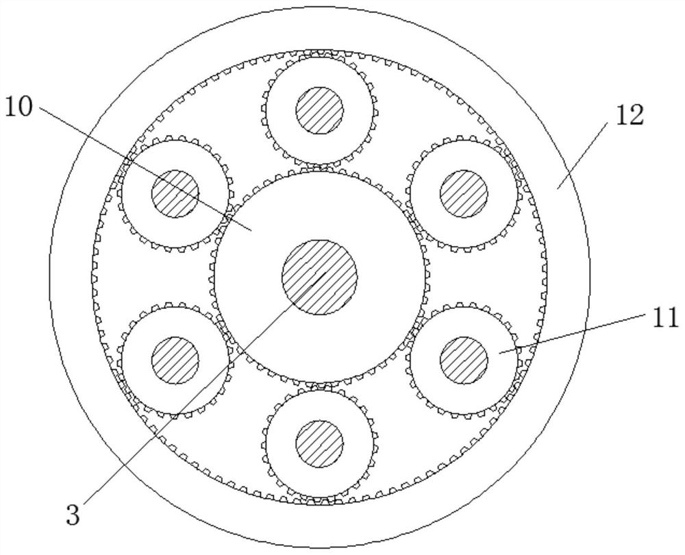
[0028] see Figure 1-5 , a combined multi-stage rotating paint powder sanding device, including a base 1, a console 2, a support frame 3, a main shaft 4, a rod 5, a crushing ball 6, a counterweight 7, a sleeve shaft 8, a feeding port 9, Main gear 10, connecting gear 11, gear ring 12, inner casing 13, unloading plate 14, telescopic device 15, sealing plate 16, feeding pipe 17, heat dissipation edge 18, water pipe 19.

[0029] The positions and connections of t...


PUM


Abstract

The invention relates to the technical field of paint, and discloses a combined multi-stage rotary paint powder sanding device. The combined multi-stage rotary paint powder sanding device comprises abase, a control console is fixedly connected to the top of the base, a supporting frame is fixedly connected to the top of the base, a main shaft is movably connected into the supporting frame, the outside of the main shaft is fixedly connected with a knock out pin, the outside of the main shaft is fixedly connected with a crushing ball, the outside of the crushing ball is fixedly connected with acounterweight, the right end of the main shaft is fixedly connected with a sleeve shaft, and a feeding inlet is movably connected into the sleeve shaft. Thorough cooperative use of the supporting frame, the main shaft, the knock out pin rod, the crushing ball, the counterweight and an inner shell, the effect of increasing collision is achieved, the efficiency of the movement of a medium inside the inner shell is improved, a collision mechanism and a collision method of the medium inside the inner shell are effectively increased, the crushing speed and crushing effect of the paint powder are improved, and the efficiency and quality of the paint powder grinding are effectively improved.

Description

technical field [0001] The invention relates to the technical field of coatings, in particular to a combined multi-stage rotating coating powder sanding device. Background technique [0002] Paint, traditionally called paint in China. The so-called paint is coated on the surface of the object to be protected or decorated, and can form a continuous film firmly attached to the object to be coated, usually based on resin, oil, or emulsion, with or without adding pigments, fillers, adding The corresponding additives are viscous liquids prepared with organic solvents or water. [0003] In the coating powder processing process, it is usually necessary to use a sand mill to grind the coating, and the existing sand mill is equipped with media for grinding such as zirconium beads, glass beads, etc. in a closed cylinder. The dispersing disc on the top moves the medium in the cylinder to make the media move relative to each other, allowing the materials to be ground to pass through t...

Claims


Application Information

Patent Timeline
IPC IPC(8): B02C17/10B02C17/16B02C17/18B02C17/20B02C17/24
CPCB02C17/10B02C17/163B02C17/1815B02C17/18B02C17/20B02C17/24
Inventor 方琬婷龚帅泓
Owner 山东鸿粤新材料有限公司
Learn More