Perforating equipment for processing aviation connector

A connector and aviation technology, which is applied in the field of opening equipment, can solve the problems of small work adaptation range, poor flexibility, poor stability of aviation connectors, etc., to achieve the effect of ensuring flexibility and preventing shaking

Active Publication Date: 2020-09-18
萧县众科电磁检测有限公司
View PDF6 Cites 1 Cited by
  • Summary
  • Abstract
  • Description
  • Claims
  • Application Information

AI Technical Summary

Problems solved by technology

[0005] The purpose of the present invention is to solve the problem that the amount of the aviation connector that can be loaded is very small and the drill bit on the aviation connector cannot quickly switch positions in order to solve the problem that the existing drilling equipment for the processing of aviation connectors is used for drilling work. Drill holes for different aviation connectors; the grasping parts on the existing drilling equipment have poor stability when grasping and moving the aviation connectors, and the aviation connectors are easy to fall and damage during the process of being moved and holed. , resulting in poor accuracy and low efficiency of the existing hole-drilling equipment for aviation connectors; The adaptable range of the drilling equipment is small; the existing drilling equipment has a low degree of automation for drilling aviation connectors, and it is time-consuming and laborious to use; the existing drilling equipment cannot flexibly change the inclination and position of the drill bit. The hole opening position of the connector is too single, and the flexibility of use is very poor, and a hole opening equipment for aviation connector processing is proposed

Method used


Image

  • Perforating equipment for processing aviation connector
  • Perforating equipment for processing aviation connector
  • Perforating equipment for processing aviation connector

Examples


Embodiment Construction

[0045] The technical solutions of the present invention will be clearly and completely described below in conjunction with the embodiments. Apparently, the described embodiments are only some of the embodiments of the present invention, not all of them. Based on the embodiments of the present invention, all other embodiments obtained by persons of ordinary skill in the art without creative efforts fall within the protection scope of the present invention.

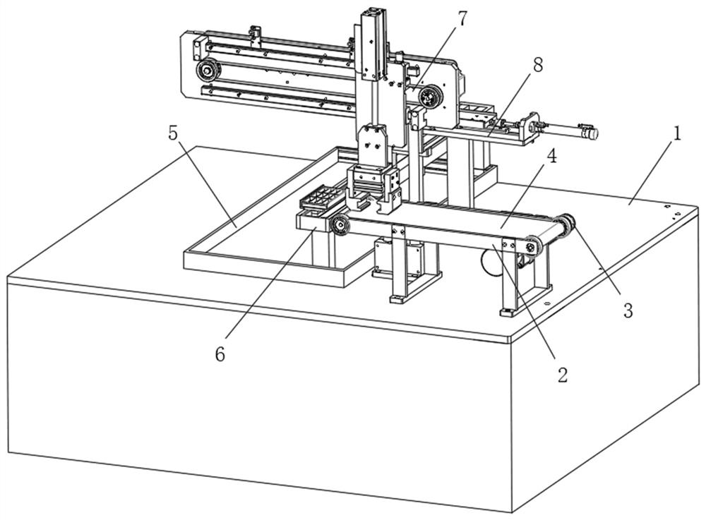
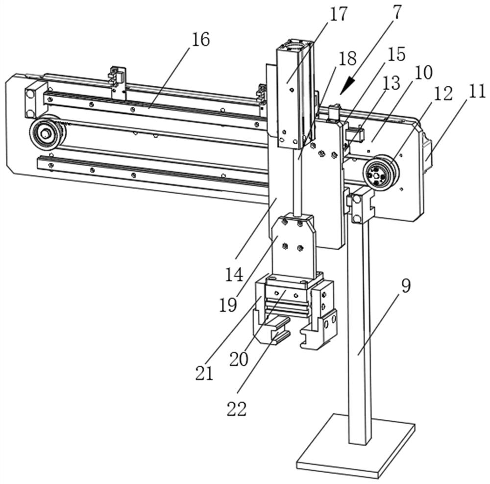
[0046] see Figure 1-11 As shown, a drilling device for aviation connector processing includes a counter 1, a conveying tray 2, a loading frame 5 and a drill floor 8, a conveying tray 2 is arranged on one side of the upper end of the counter 1, and one side of the conveying tray 2 A loading frame 5 in the shape of a hollow cuboid is arranged below, and a moving support 6 is sleeved in the loading frame 5, and a grabbing frame 7 is arranged between the conveying tray 2 and the loading frame 5, and one side of the grabbing fr...


PUM


Abstract

The invention discloses perforating equipment for processing an aviation connector. The equipment comprises a workbench, a conveying tray, a loading frame and a drill floor, the conveying tray is arranged on one side of the upper end face of the workbench, and the loading frame of a hollow cuboid-shaped structure is arranged below one side of the conveying tray. The equipment has the beneficial effects that after a loading plate is moved onto a support frame of a moving bracket, a hydraulic cylinder III drives a pushing and clamping plate to move through a hydraulic shaft III to clamp the sidewall of the loading plate, so as to ensure that the aviation connector in the loading plate is firmer and more stable during perforating process, a motor V drives a gear II to roll in a gear hobbingslot II of a sliding slot II, and drives the loading plate on the moving bracket to move below a drill bit of the drill floor, a hydraulic cylinder IV drives a pushing sliding frame and the drill bitto move through a hydraulic shaft IV, the drill bit is moved above the aviation connector, a hydraulic cylinder V drives the drill bit to move downwards, a motor VII drives the drill bit to rotate forhole-drilling and perforating of the aviation connector, the equipment is high in degree of automation for perforating treatment of the aviation connector, and time and effort are saved.

Description

technical field [0001] The invention relates to a hole-drilling device, in particular to a hole-drilling device for processing aviation connectors, and belongs to the application technical field of hole-drilling devices for processing aviation connectors. Background technique [0002] Aviation connectors are widely used in navigation, aerospace, aviation and other fields. The shell materials are often made of magnesium aluminum alloy, stainless steel, etc., which are durable. Aviation connectors are used for connection and assembly of equipment parts. [0003] In the processing of aviation connectors, drilling equipment is indispensable. The drilling equipment is used to drill and open holes in the aviation connectors to ensure that the aviation connectors can be better and more firmly adapted to the equipment components when they are used later. with installation. [0004] There are still many deficiencies in the existing drilling equipment for the processing of aviation c...

Claims


Application Information

Patent Timeline
Patent Type & Authority Applications(China)
IPC IPC(8): B23B41/00B23Q7/00B23Q7/04B23Q1/25
CPCB23B41/00B23Q1/25B23Q7/00B23Q7/003B23Q7/04B23Q7/043
Inventor 周伟伟
Owner 萧县众科电磁检测有限公司
Why Eureka
Try Eureka