Laser device for material formation

A laser equipment and material forming technology, applied in laser welding equipment, welding equipment, metal processing equipment and other directions, can solve the problems of residual dust on the surface of the material, uneven surface, affecting the actual use, etc., to improve convenience, convenient and stable observation Effect

Inactive Publication Date: 2020-09-18
袁福德
View PDF0 Cites 0 Cited by
  • Summary
  • Abstract
  • Description
  • Claims
  • Application Information

AI Technical Summary

Problems solved by technology

[0003] In the process of laser rapid prototyping for engraving and printing, the material to be processed will be placed on the top of the processing table. Since the top of the processing table will be exposed, the engraving probe will be suspended on the surface of the processed material to print the molding material. Use the accumulation of paint to achieve the effect of material molding, but the exposed environment will cause dust to remain on the surface of the material. In laser printing and engraving, more dust will affect the actual accumulation of printed materials, resulting in uneven surfaces and affecting actual use.

Method used


Image

  • Laser device for material formation
  • Laser device for material formation
  • Laser device for material formation

Examples


Embodiment Construction

[0029] The following will clearly and completely describe the technical solutions in the embodiments of the present invention with reference to the accompanying drawings in the embodiments of the present invention. Obviously, the described embodiments are only some, not all, embodiments of the present invention. Based on the embodiments of the present invention, all other embodiments obtained by persons of ordinary skill in the art without making creative efforts belong to the protection scope of the present invention.

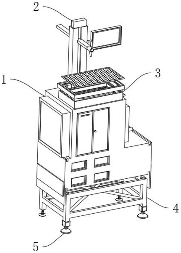
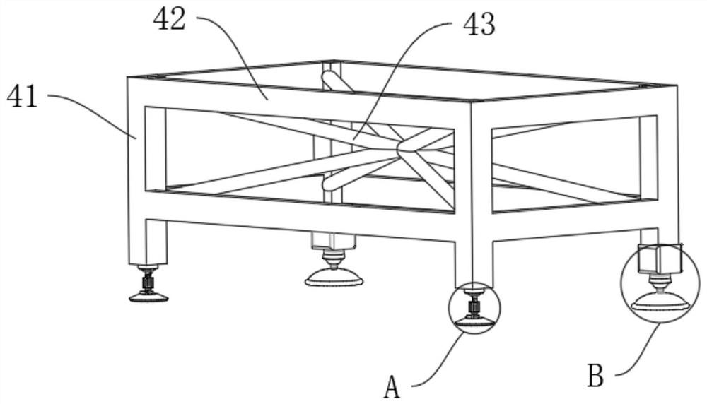
[0030] Refer to the attached Figure 1-10 , a laser device for material forming according to an embodiment of the present invention may include a laser forming mechanism 1, the top of the laser forming mechanism 1 is fixed with a control mechanism 2 by bolts, and both the laser forming mechanism 1 and the control mechanism 2 are CHUKE series laser Rapid prototyping engraving machine, one side of the control mechanism 2 is fixedly installed with the console mec...


PUM


Abstract

The invention discloses a laser device for material formation, and particularly relates to the field of laser formation. The laser device for material formation comprises a laser formation mechanism.A control mechanism is fixedly mounted at the top of the laser formation mechanism through bolts. An operating table mechanism is fixedly mounted on one side of the control mechanism and is fixedly mounted at the top of the laser formation mechanism through bolts. A supporting mechanism is fixedly mounted at the bottom of the laser formation mechanism through bolts. An adjustment mechanism is fixedly mounted at the bottom of the supporting mechanism through bolts. The operating table mechanism comprises an air blower which is fixedly mounted on one side of the laser formation mechanism throughbolts. According to the laser device for material formation, the operating table mechanism is arranged, a concave air guide table allows the air flow in a cavity of a moving groove to form an arc track, and dust near machined materials enter the cavity of the moving groove via a punched groove and is finally discharged by the air blower, so that the quality of a finished product machined from thematerials is improved relatively.

Description

technical field [0001] The invention relates to the technical field of laser shaping, and more specifically, the invention relates to a laser device for material shaping. Background technique [0002] Laser rapid prototyping is a new manufacturing technology that integrates advanced technologies such as CAD, CAM, CNC, laser, precision servo drive and new materials. It has nothing to do with the geometric shape of the manufacturing prototype, the processing cycle is short, the cost is low, the general manufacturing cost is reduced by 50%, the processing cycle is shortened by more than 70%, a high degree of technology integration, and the integration of design and manufacturing is realized. SLA technology is also called light-curing rapid prototyping technology. The principle is that the computer controls the laser beam to scan the surface of the photosensitive resin point by point, and the thin layer of the resin in the scanned area is about a few tenths of a millimeter to pr...

Claims


Application Information

Patent Timeline
Patent Type & Authority Applications(China)
IPC IPC(8): B23K26/142B23K26/362B23K26/70
CPCB23K26/362B23K26/142B23K26/702
Inventor 袁福德时光
Owner 袁福德
Why Eureka
Try Eureka