
Clamp with shock absorption function for precision machine tool

A technology of precision machine tools and utensils, used in clamping, manufacturing tools, metal processing mechanical parts, etc., can solve the problems of low production efficiency, low qualified rate of workpiece products, inconvenient machine tool processing, and product quality problems, and achieves a reduction in production efficiency. Small vibration, convenient control, and the effect of improving machining accuracy

Active Publication Date: 2020-09-18
GUIZHOU UNIV OF ENG SCI
View PDF13 Cites 1 Cited by
  • Summary
  • Abstract
  • Description
  • Claims
  • Application Information

AI Technical Summary

Problems solved by technology

In the process of modern industrial production, fixtures have been widely used in the process of machine tool processing. When clamping workpieces, if the fixtures cannot fix the workpieces well, it will cause problems in the quality of the products, and the size is prone to deviation. As a result, the production efficiency and the qualified rate of the workpiece products are not high. In the prior art, although the clamps for machine tools can achieve the effect of clamping the workpiece, in the actual processing process, affected by the position of the tool, the distance between the workpiece clamp and the tool There is a relatively slight amplitude between them, and vibrations of different frequencies appear when the rotation rate of the workpiece is too high or low, which brings great inconvenience to people's machining work on the workpiece. Therefore, it is necessary to propose a precision machine tool with shock absorption function of the fixture to address the above

Method used


Image

  • Clamp with shock absorption function for precision machine tool
  • Clamp with shock absorption function for precision machine tool
  • Clamp with shock absorption function for precision machine tool

Examples


Embodiment Construction

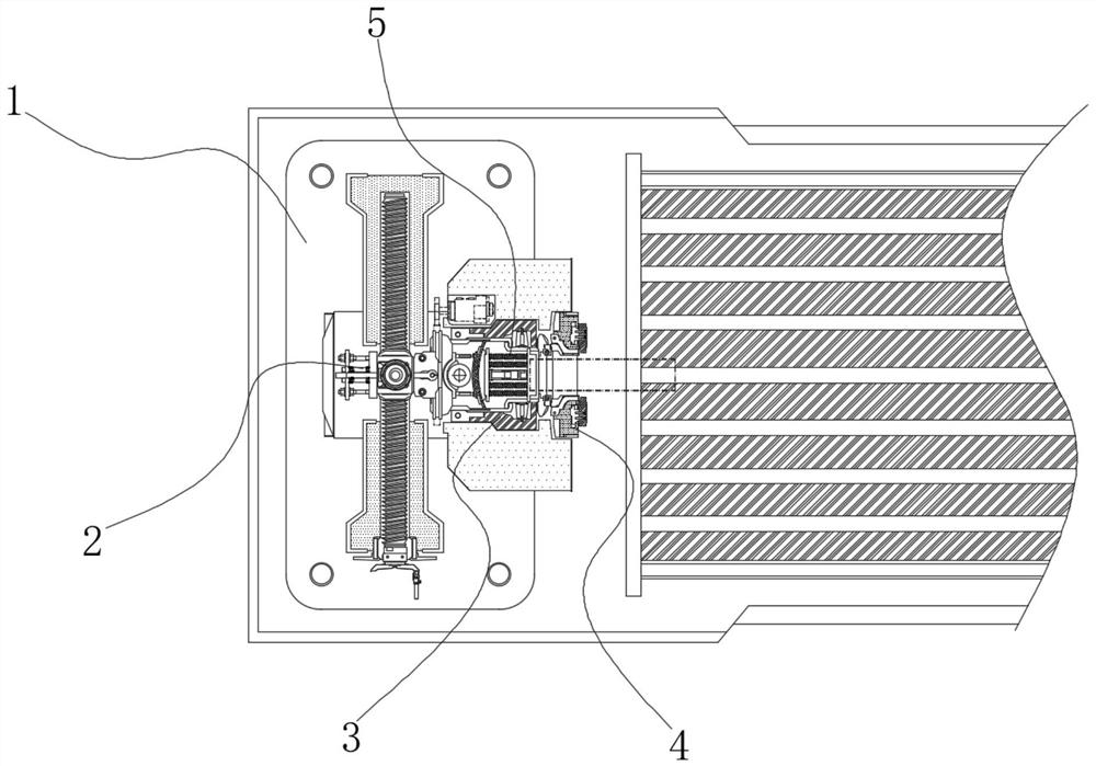
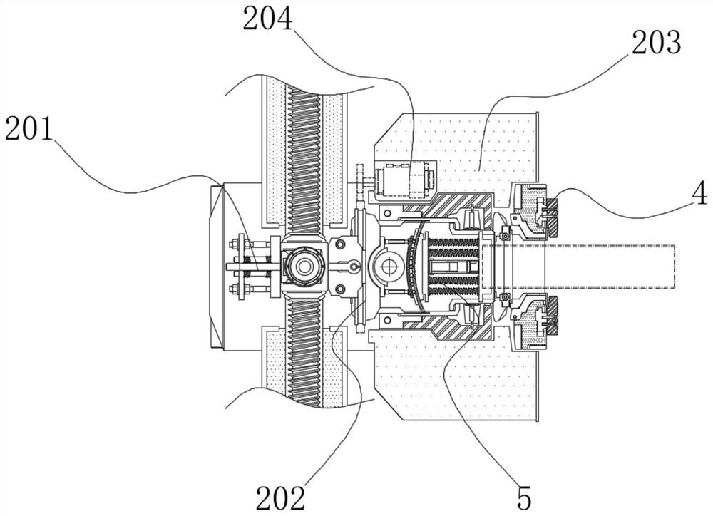
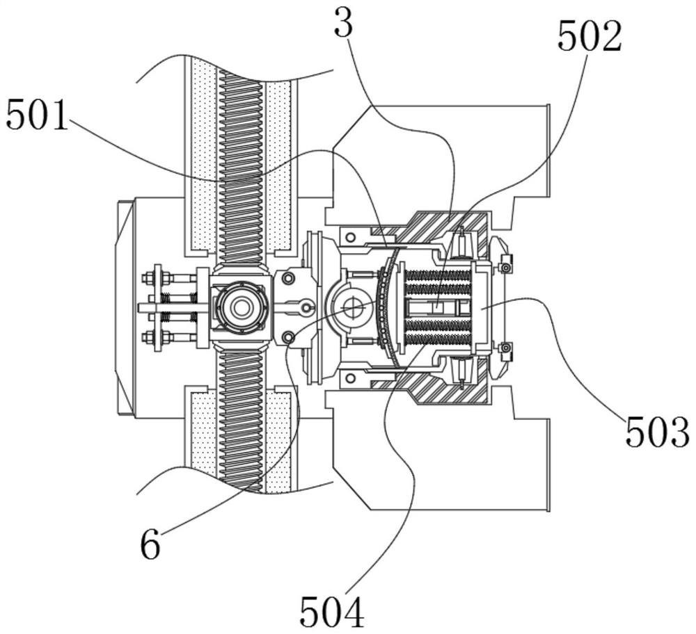
[0035] refer to figure 1 , the present invention provides a technical solution: a jig with a shock-absorbing function for a precision machine tool, which includes a fixed base 1, a support base 2, a mechanical jaw plate 4, a phase buffer assembly 5, and a sliding limit assembly 3, wherein the The fixed base 1 is fixed on one side of the upper end surface of the machine tool workbench by bolts, and a support base 2 is installed above the fixed base 1. It is characterized in that: a mechanical claw plate 4 is installed in the horizontal direction of the support base 2, so that The mechanical claw plate 4 is clamped and fixed at one end of the workpiece to be processed;

[0036] A phase buffer assembly 5 is also arranged between the support base 2 and the mechanical claw plate 4, and the phase buffer assembly 5 slows down the vibration received by the mechanical claw plate 4 as a whole, so that the workpiece to be processed is transmitted to the mechanical claw plate during proce...


PUM


Abstract

The invention discloses a clamp with a shock absorption function for a precision machine tool. The clamp comprises a fixed base, a support pedestal, a mechanical claw, a phase buffer assembly and a sliding limiting assembly, wherein the fixed base is fixedly arranged at one side of an upper end face of a machine tool worktable by bolts, the support pedestal is installed above the fixed base, the mechanical claw is horizontally installed in the support pedestal, the phase buffer assembly is also arranged between the support pedestal and the mechanical claw, and the phase buffer assembly can slow down the overall external vibration of the mechanical claw, so that vibration transmitted to the mechanical claw from a workpiece to be processed during processing is transformed into a lateral offset variable to a certain extent; and an outer casing of the phase buffer assembly is provided with the sliding limiting component, when the sliding limiting assembly slides in the mechanical claw horizontally along with the phase buffer assembly, the sliding limiting assembly can limit and fix the mechanical claw, and the workpiece to be processed can be shock-absorbed and buffered within a deviation range.

Description

technical field [0001] The invention relates to the technical field of machine tool fixtures, in particular to a precision machine tool fixture with a shock-absorbing function. Background technique [0002] Precision machine tool is a high-efficiency automatic machine tool, which represents the development direction of modern machine tool control technology. It has been widely used in modern industry, which greatly improves the production efficiency of enterprises. With the continuous development of society, machine tool Technology plays an irreplaceable role in social production. When processing a workpiece, it must be fixed so that it is in the correct processing position to facilitate drilling, tapping and other processes. In the process of modern industrial production, fixtures have been widely used in the process of machine tool processing. When clamping workpieces, if the fixtures cannot fix the workpieces well, it will cause problems in the quality of the products, an...

Claims


Application Information

Patent Timeline
Patent Type & Authority Applications(China)
IPC IPC(8): B23Q3/06B23Q11/00
CPCB23Q3/06B23Q11/00B23Q11/0032
Inventor 陈华李江赵国旗许晋
Owner GUIZHOU UNIV OF ENG SCI
Learn More