Eureka AIR delivers breakthrough ideas for toughest innovation challenges, trusted by R&D personnel around the world.

Concrete mixer with power saving function

A concrete mixer and functional technology, applied in the field of new energy-saving equipment, can solve problems such as energy waste and mixing resistance, and achieve the effects of reducing consumption, reducing resistance and prolonging life.

Inactive Publication Date: 2020-09-18
杭州摩亚机械科技有限公司
View PDF0 Cites 0 Cited by
  • Summary
  • Abstract
  • Description
  • Claims
  • Application Information

AI Technical Summary

Problems solved by technology

[0002] In industries such as construction, the demand for concrete is very large, and a layer of solidified concrete will remain on the inner wall of the concrete mixer during long-term mixing, which will cause great resistance to subsequent mixing, resulting in a waste of energy

Method used


Image

  • Concrete mixer with power saving function
  • Concrete mixer with power saving function
  • Concrete mixer with power saving function

Examples


Embodiment Construction

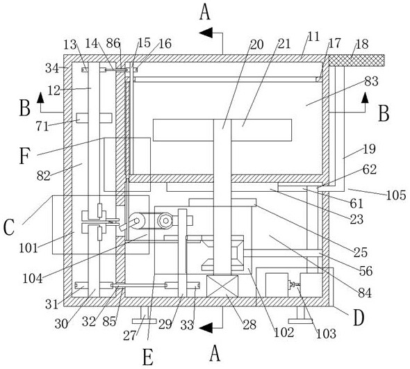
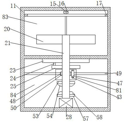
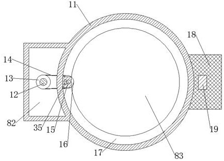
[0020] Combine below Figure 1-Figure 7 The present invention is described in detail, and for convenience of description, the orientations mentioned below are now stipulated as follows: figure 1 The up, down, left, right, front and back directions of the projection relationship itself are the same.

[0021] A concrete mixer with power-saving function according to the present invention comprises a main box body 11, a mixing chamber 83 is arranged inside the main box body 11, and an upper belt opening facing left is provided at the upper end of the left wall of the mixing chamber 83. Wheel chamber 86, the left end of the lower wall of the stirring chamber 83 is provided with a slide chamber 87 opening to the left, the lower end of the stirring chamber 83 is connected with the power chamber 84 through the slide chamber 87, and the lower end of the left wall of the power chamber 84 is provided with There is a lower pulley chamber 85 with an opening to the left. The left side of t...


PUM


Abstract

The invention discloses a concrete mixer with a power saving function. The concrete mixer comprises a main box body, wherein a mixing cavity is formed in the main box body; an upper belt wheel cavitywith a leftward opening is formed in the upper end of the left wall of the mixing cavity; a sliding plate cavity with a leftward opening is formed in the left end of the lower wall of the mixing cavity; a power cavity is formed in the lower end of the mixing cavity through the sliding plate cavity in a communicating manner; a lower belt wheel cavity with a leftward opening is formed in the lower end of the left wall of the power cavity; a transmission cavity is formed in the left side of the upper belt wheel cavity in a communicating manner; a screw rod is rotationally connected to the left side of the mixing cavity and the upper and lower walls of the mixing cavity; a first driven belt wheel is fixedly connected to the outer circular surface of the upper end of the screw rod; and a scraper blade capable of sliding up and down on the two side walls of the mixing cavity is connected to the outer circular surface of the upper end of the screw rod and below the first driven belt wheel ina threaded fit manner. According to the concrete mixer, the resistance of mixing blades is reduced by scraping off concrete adhered and solidified on the inner wall of the mixing cavity discontinuously, so that the purpose of saving power is achieved.

Description

technical field [0001] The invention relates to the technical field of new power-saving equipment, in particular to a concrete mixer with power-saving function. Background technique [0002] In construction and other industries, the demand for concrete is very large, and a layer of solidified concrete will remain on the inner wall of the concrete mixer during long-term mixing, which will cause great resistance to subsequent mixing, resulting in waste of energy. The present invention illustrates a device capable of solving the above-mentioned problems. Contents of the invention [0003] Technical problem: The inner wall of the concrete mixer is easy to solidify a layer of residual concrete during long-term use, which will produce resistance to the mixing of the mixer and consume energy. [0004] In order to solve the above problems, a concrete mixer with power-saving function is designed in this example. A concrete mixer with power-saving function in this example includes ...

Claims


Application Information

Patent Timeline
Patent Type & Authority Applications(China)
IPC IPC(8): B28C5/16B28C5/08B08B9/087H02J7/14H02J7/35H02J9/06
CPCB08B9/0808B28C5/0806B28C5/0831B28C5/16H02J7/1423H02J7/35H02J9/062Y02B70/30Y04S20/20
Inventor 黎城
Owner 杭州摩亚机械科技有限公司
Why Eureka
Eureka Blog
Learn More