Novel metallurgical embedded scraper transporter special tail device

A buried scraper conveyor and a new type of technology, applied in the field of special tail devices for new metallurgical buried scraper conveyors, can solve the problems of equipment operation obstruction, tail accumulation, irregular shape, etc., and achieve easy popularization, efficiency improvement, manufacturing low cost effect

Active Publication Date: 2020-09-18
宜昌新宜运机械有限公司
View PDF7 Cites 0 Cited by
  • Summary
  • Abstract
  • Description
  • Claims
  • Application Information

AI Technical Summary

Problems solved by technology

Buried scraper conveyors are used more and more frequently in today's production and transportation. The most common buried scraper conveyors mainly rely on the discharge port of the head to discharge materials, which are limited by the space inside the conveyor. The material has a certain effect, but in the metallurgical industry, the shape of the mined material is not only irregular but also generally large in size, which requires relatively high requirements on the conveyor. Once the material volume is too large during the transportation process, it is easy to The problem of tail hoarding is caused, and the material cannot be effectively transported to the discharge port to be unloaded. At the same time, the operation of the equipment is hindered, causing the conveyor belt to jam. Faced with this phenomenon, we must adopt a new solution and make corresponding changes

Method used


Image

  • Novel metallurgical embedded scraper transporter special tail device
  • Novel metallurgical embedded scraper transporter special tail device

Examples


Embodiment 1

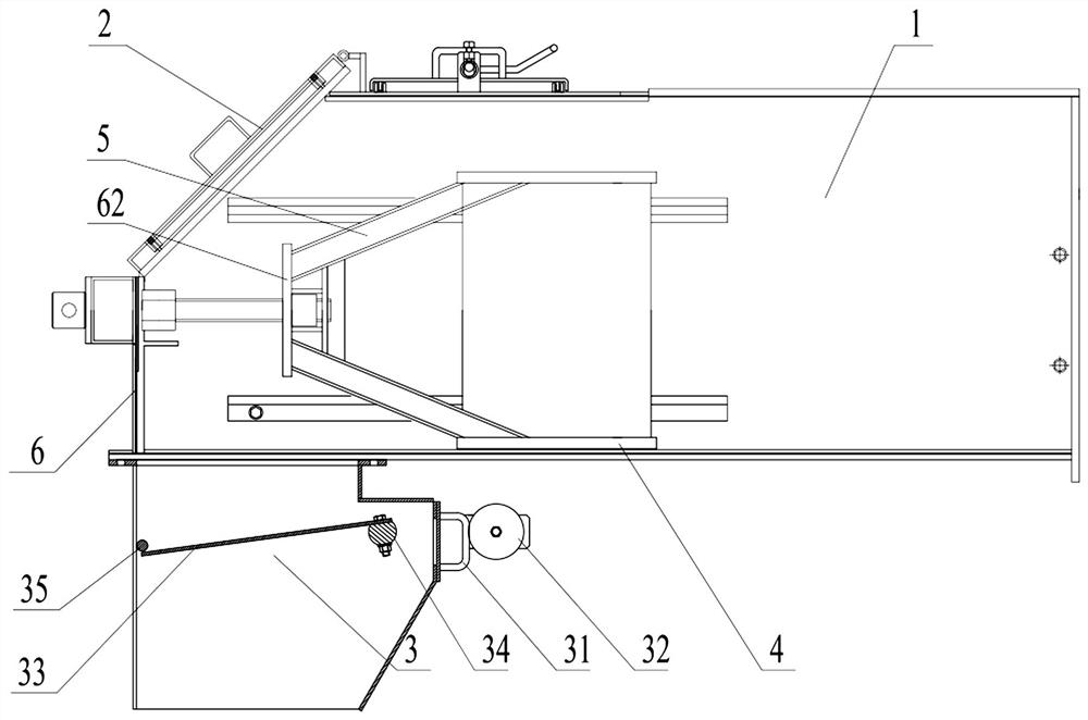
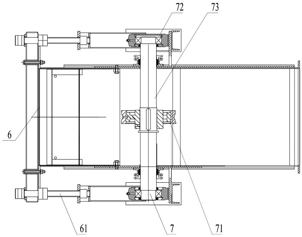
[0019] like Figure 1~2 As shown, a new special tail device for metallurgical buried scraper conveyor includes a casing 1 and a transmission mechanism 7, the casing 1 includes a heavy hammer door 2, and the heavy hammer door 2 is located on the upper part of the casing 1, so The casing 1 is provided with a slide plate 4 along the moving direction of the conveyor scraper, and the lower part of the casing 1 is fixed with a gravity flap mechanism 3 . With this structure, after the tail of the conveyor is completed, the heavy hammer door 2 can be manually opened to complete the unloading, or the sliding slide 4 can be used to complete the unloading on the side of the conveyor. The unloading process at the bottom of the machine.

[0020] In a preferred solution, one end of the heavy hammer door 2 is connected to the housing 1 through a hinge, and a door handle is provided on the heavy hammer door 2 . With this structure, large materials can complete the material unloading process...

Embodiment 2

[0030] Further illustrate according to embodiment 1, as Figure 1~2 Shown:

[0031] The material falls from the head of the metallurgical buried scraper conveyor into the interior of the shell 1, and is transported to the tail under the operation of the transmission mechanism 7. Due to the heavy weight and irregular shape of the metallurgical material, it is easy to form the accumulation and accumulation of the tail material. Congestion, by setting the mass of the counterweight 32 on the gravity turnover mechanism 3, when a part of the material with a small volume accumulates to exceed the weight of the turnover action as a whole, the material will push the turnover panel 33 to open under the action of gravity, and this will be automatically completed. When some materials are unloaded and other parts with larger volume are piled up, the rear baffle 6 can be pulled. At this time, the partition moves in the direction of the rear baffle 6. During the operation, openings are forme...


PUM


Abstract

The invention provides a novel metallurgical embedded scraper transporter special tail device including a shell body and a transmission mechanism. The shell body includes a heavy hammer door, the heavy hammer door is located above the shell body, a sliding plate is arranged on the shell body along the moving direction of a transporter scraper, and a gravitational turning plate mechanism is fixedlyarranged below the shell body. According to the device, a multi-directional discharging structure is adopted to discharge with convenience and high efficiency, and the flexibility in the material transporting and discharging process is improved.

Description

technical field [0001] The invention belongs to the field of metallurgical buried scraper conveyors, and in particular relates to a new special tail device for metallurgical buried scraper conveyors. Background technique [0002] With the development of the times and the advancement of technology, the requirements for material transportation are getting higher and higher, and the degree of automation is becoming more and more popular. Buried scraper conveyors are used more and more frequently in today's production and transportation. The most common buried scraper conveyors mainly rely on the discharge port of the head to discharge materials, which are limited by the space inside the conveyor. The material has a certain effect, but in the metallurgical industry, the shape of the mined material is not only irregular but also generally large in size, which requires relatively high requirements on the conveyor. Once the material volume is too large during the transportation pro...

Claims


Application Information

Patent Timeline
Patent Type & Authority Applications(China)
IPC IPC(8): B65G47/34B65G47/44B65D88/66
CPCB65G47/34B65G47/44B65D88/66
Inventor 伍阳陶伟范生旺
Owner 宜昌新宜运机械有限公司
Why Eureka
Try Eureka