Plastic drum stacking machine and stacking method

A plastic bucket and stacking technology, applied in the field of stacking machines for stacking objects, can solve problems such as low production efficiency, loose stacking, and narrow application range, and achieve the goals of improving stacking efficiency, expanding application range, and improving accuracy Effect

Active Publication Date: 2020-09-18
JIANGSU UNIV OF SCI & TECH
View PDF6 Cites 6 Cited by
  • Summary
  • Abstract
  • Description
  • Claims
  • Application Information

AI Technical Summary

Problems solved by technology

[0003] At present, in order to realize the close stacking of objects, the stacking equipment on the market uses suction cups to absorb the top surface of the stacked objects. Since the top surface of the plastic bucket is a plastic bucket cover, during the stacking process of the plastic bucket, currently The common stacking equipment is not competent, so the enterprise can only stack plastic barrels manually, the labor intensity of the workers is high, and the production efficiency is low
[0004] The patent No. 201820252674.4 discloses a technical solution for automatic stacking equipment for metal barrels, which uses three barrel clamps to clamp metal barrels and then stacks them. This technical solution has the following technical problems: 1. Only one barrel can be stacked at a time. Metal barrels have low stacking efficiency; 2. Only metal barrels of the same specification can be stacked, and the application range of the equipment is narrow; 3. Three metal barrels are clamped by the barrel clamps. Due to the interference of the barrel clamps, the stacking There must be a large enough gap between the stacked metal drums, otherwise the drum holding clip cannot be pulled out, resulting in a large gap between the stacked metal drums and a loose stack

Method used


Image

  • Plastic drum stacking machine and stacking method
  • Plastic drum stacking machine and stacking method
  • Plastic drum stacking machine and stacking method

Examples


Embodiment

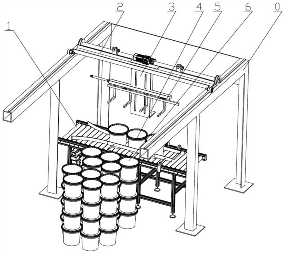
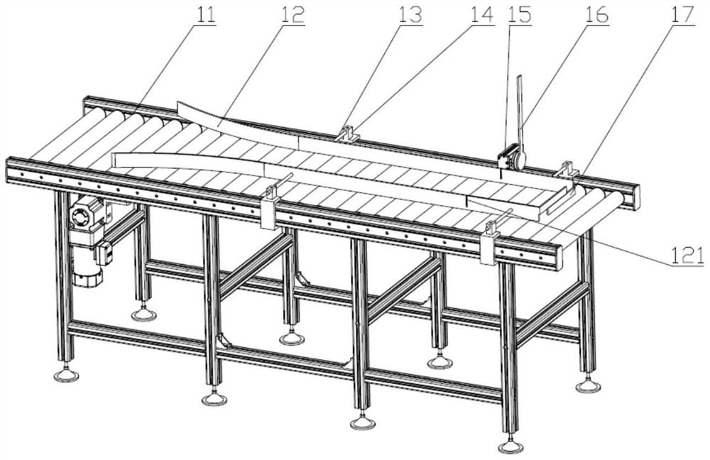
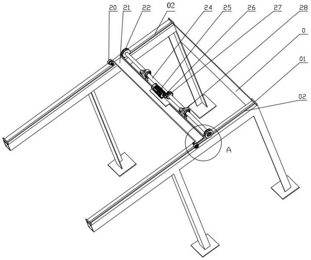
[0049] Such as figure 1 , figure 2 and image 3 As shown, a plastic barrel stacking machine includes a support frame 0, an assembly line part 1, a horizontal moving part 2, a vertical moving part 3, a plastic barrel 4 and an actuator part 5, and the top of the supporting frame 0 is provided with double Arms, the top surface of the arms of the support frame 0 is equipped with guide rails 02, the horizontal moving part 2 straddles the two guide rails 02 and can move along the guide rails 02; the top of the vertical moving part 3 Fixedly installed on the bottom surface of the horizontal moving part 2, the vertical moving part 3 is provided with a chute 331 along the vertical direction, the vertical driving part 3 is equipped with a vertical driving plate 37, and the vertical driving plate 37 can move along the vertical direction. The chute 331 moves; the actuator part 5 includes a cylinder 51, an actuator mounting bracket 52 and a gripper assembly 53, the actuator mounting bra...


PUM


Abstract

The invention provides a plastic drum stacking machine. The plastic drum stacking machine comprises a supporting frame, an assembly line part, a horizontal movement part, a vertical movement part, plastic drums and an executing part. Double arms are arranged on the top of the supporting frame in parallel, guide rails are mounted on the top faces of the double arms of the supporting frame, and thehorizontal movement part stretches over the two guide rails and can move along the guide rails. The top of the vertical movement part is fixedly mounted on the bottom face of the horizontal movement part, the vertical movement part is provided with a sliding groove in the vertical direction, the vertical movement part is provided with a vertical drive plate, and the vertical drive plate can move along the sliding groove. The executing part comprises an air cylinder, an executing part mounting support and a paw assembly, and the executing part mounting support is connected with the vertical drive plate. The assembly line part is arranged below the inner sides of the double arms of the supporting frame. By adjusting the interval between paws, the plastic drum stacking machine can be suitablefor stacking the plastic drums with different sizes, two or three plastic drums can be stacked at a time, and the stacking efficiency is greatly improved.

Description

technical field [0001] The invention relates to a stacking machine for stacking objects, in particular to a stacking machine for cylindrical objects. Background technique [0002] In the field of waterproof coatings, plastic buckets are widely used to hold water-based and powder-based packages for the transportation and storage of water-based and powder-based packages. The plastic barrels of the package and the powder package are stacked together according to certain rules, and then the plastic barrels stacked together are wrapped with a film, and then packed. [0003] At present, in order to realize the close stacking of objects, the stacking equipment on the market uses suction cups to absorb the top surface of the stacked objects. Since the top surface of the plastic bucket is a plastic bucket cover, during the stacking process of the plastic bucket, currently Common stacking equipment is not up to the task, so enterprises can only manually stack plastic barrels. The lab...

Claims


Application Information

Patent Timeline
Patent Type & Authority Applications(China)
IPC IPC(8): B65G61/00B65G47/28B65B35/50B65B35/42
CPCB65B35/42B65B35/50B65G47/28B65G61/00B65G2201/0241
Inventor 齐继阳张艳琼张宇超刘昊
Owner JIANGSU UNIV OF SCI & TECH
Why Eureka
Try Eureka