Plastic foam conveying equipment

A technology of conveying equipment and plastic foam, applied in the field of plastic foam production, can solve the problems of reducing the quality of plastic foam, screening of beads, different sizes, etc., and achieve the effect of improving efficiency and quality

Inactive Publication Date: 2020-09-18
杨志银
View PDF0 Cites 2 Cited by
  • Summary
  • Abstract
  • Description
  • Claims
  • Application Information

AI Technical Summary

Problems solved by technology

[0003] However, when the existing plastic foam raw material beads are transported, the size of the beads cannot be screened, resulting in different sizes after subsequent foaming and reducing the quality of the plastic foam after molding

Method used


Image

  • Plastic foam conveying equipment
  • Plastic foam conveying equipment
  • Plastic foam conveying equipment

Examples


Embodiment Construction

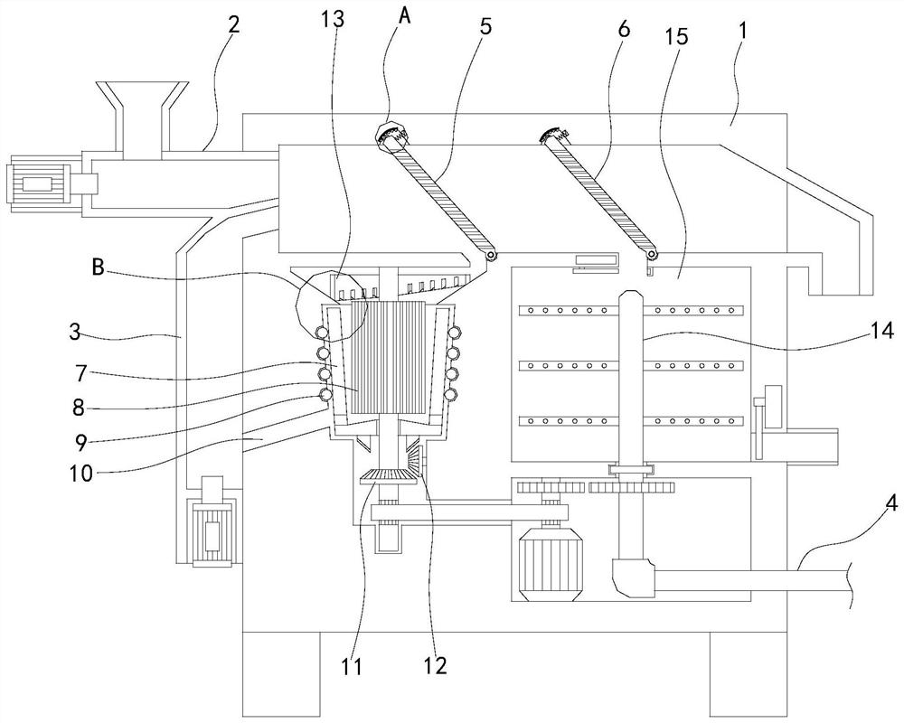
[0025] see Figures 1 to 6 , a schematic diagram of a planar structure and a schematic diagram of a three-dimensional structure of a plastic foam conveying device.

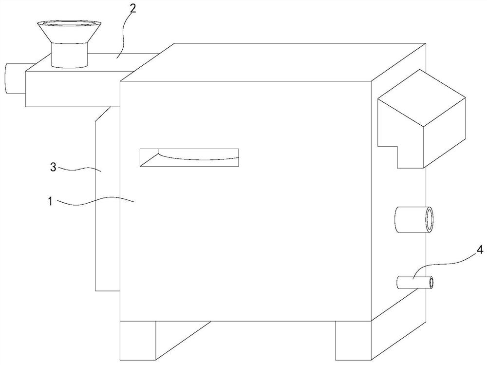
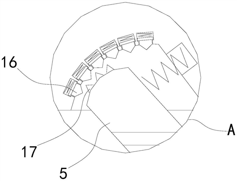
[0026] A plastic foam conveying device, comprising a device main body 1, a first filter plate 5 is movably installed on the upper end of the device main body 1, a rotating column 8 is fixedly installed on the left side of the device main body 1, and the left side of the device main body 1 is relatively to the rotating column 8. A bead grinding cylinder 7 is fixedly installed on the outside, and a baffle plate 13 is fixedly installed on the inside of the device main body 1 relative to the top of the rotating column 8 .

[0027] In specific implementation, the feed pipe 2 is fixedly installed on the upper left side of the device main body 1, and the second filter plate 6 is movably installed on the right side of the upper end inside the device main body 1, and the diameter of the through hole in the second filter pl...


PUM


Abstract

The invention relates to the field of plastic foam production, in particular to plastic foam conveying equipment which comprises a device main body. A first filter plate is movably installed at the upper end inside the device main body, a rotating column is fixedly installed at the left side inside the device main body, a bead grinding cylinder is fixedly installed at the left side inside the device main body relative to the outer side of the rotating column, and a baffle plate is fixedly installed inside the device main body relative to the upper part of the rotating column. A convex block isfixedly installed at the upper end of the first filter plate, and an inner shrinkage block engaged with the convex block is movably installed inside the upper end of the device main body, so that when the first filter plate is used for a long time and some raw material beads are clamped in the first filter plate, the first filter plate is driven to rotate with the lower end as the center by increasing the air exhaust speed of a fan, then, the rotating speed of the fan is reduced, the first filter plate returns under the effect of a right spring, the convex block collides with the inner shrinkage block to produce vibration with the certain frequency, the clamped raw material beads are vibrated out, and an automatic cleaning effect is achieved.

Description

technical field [0001] The invention relates to the field of plastic foam production, in particular to a plastic foam conveying device. Background technique [0002] Rigid foam plastic refers to the foam plastic that has no flexibility, high compression hardness, deformation when the stress reaches a certain value, and cannot return to its original shape after the stress is released. It is often used in related fields by using its heat insulation and mechanical properties. Now when producing hard plastics, it is necessary to first heat the raw material beads with steam to above 92°C to soften and foam, so that the internal blowing agent volatilizes and escapes the particles. The volume slowly expands to the required ratio or gram weight, and then the foam is heated by steam after a certain mold is filled, and can be fused into a molded product with a fixed shape. [0003] However, when the existing plastic foam raw material beads are transported, the size of the beads canno...

Claims


Application Information

Patent Timeline
Patent Type & Authority Applications(China)
IPC IPC(8): B65G65/32B07B1/04B24B11/02B01F7/18
CPCB65G65/32B07B1/04B24B11/02B01F27/90
Inventor 杨志银
Owner 杨志银
Why Eureka
Try Eureka