Intelligent efficient energy-saving sludge treatment device

A high-efficiency, energy-saving, sludge treatment technology, applied in sludge treatment, water/sludge/sewage treatment, dehydration/drying/thickened sludge treatment, etc. Good adaptation to deal with conditions and other issues

Pending Publication Date: 2020-09-18
WUXI SANHE HEAVY MACHINERY
View PDF0 Cites 0 Cited by
  • Summary
  • Abstract
  • Description
  • Claims
  • Application Information

AI Technical Summary

Problems solved by technology

[0004] The purpose of the present invention is to provide an intelligent high-efficiency and energy-saving sludge treatment device to solve the problem that the structure of the main body of the existing sludge treatment device proposed in the above-mentioned background technology is not compact enough, resulting in large distribution of the main body structure and space gaps. Many, the overall space of the main body is huge, and it is not convenient for use and assembly. At the same time, the sludge treatment method of the main body is single, resulting in poor sludge treatment effect, and cannot be well adapted to different treatment conditions, etc.

Method used


Image

  • Intelligent efficient energy-saving sludge treatment device
  • Intelligent efficient energy-saving sludge treatment device
  • Intelligent efficient energy-saving sludge treatment device

Examples


Embodiment Construction

[0026] The following will clearly and completely describe the technical solutions in the embodiments of the present invention with reference to the accompanying drawings in the embodiments of the present invention. Obviously, the described embodiments are only some, not all, embodiments of the present invention.

[0027] In the description of the present invention, unless otherwise stated, the meaning of "plurality" is two or more; the terms "upper", "lower", "left", "right", "inner", "outer" , "front end", "rear end", "head", "tail", etc. indicate the orientation or positional relationship based on the orientation or positional relationship shown in the drawings, and are only for the convenience of describing the present invention and simplifying the description, rather than Nothing indicating or implying that a referenced device or element must have a particular orientation, be constructed, and operate in a particular orientation should therefore not be construed as limiting ...


PUM


Abstract

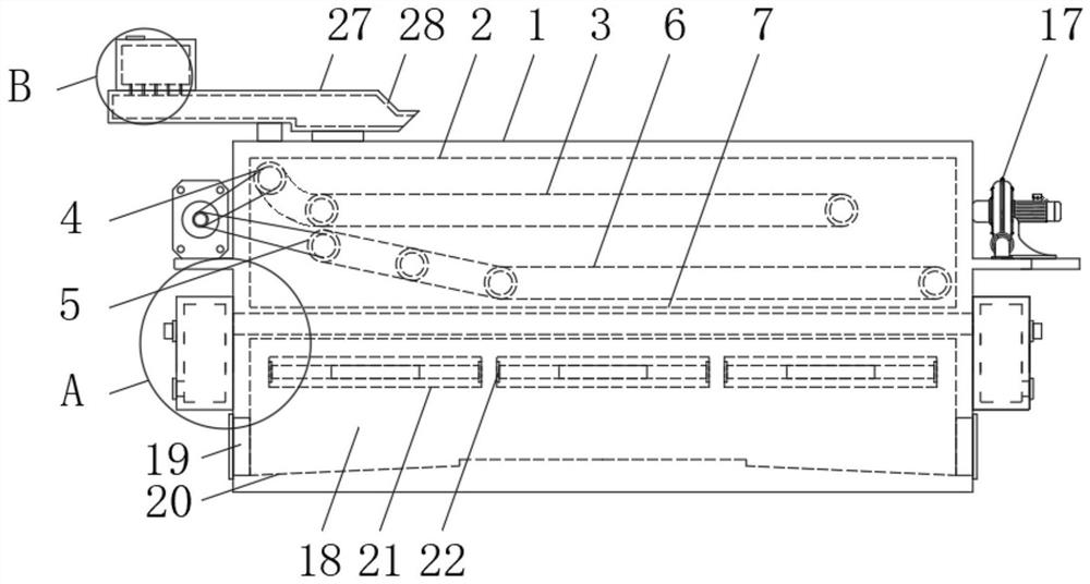
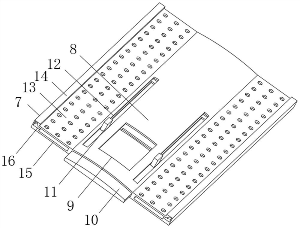
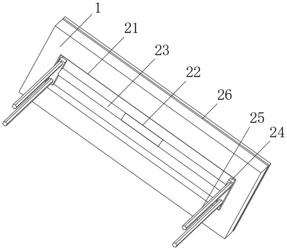
The invention relates to an intelligent efficient energy-saving sludge treatment device. The device comprises a device body and a halving mechanism, wherein an upper chamber and a lower-stage treatment chamber are respectively formed in the upper end and the lower end of the device body, an upper filter belt is installed at the top end of the interior of the upper chamber, an upper rolling cylinder is installed on the left end side of the upper filter belt in a matched mode, a lower rolling cylinder is arranged on the lower side of the left end of the upper filter belt, a lower filter belt isinstalled at the end of the lower rolling cylinder in a matched and sleeved mode, and the halving mechanism is arranged at the bottom end of the upper chamber. The intelligent efficient energy-savingsludge treatment device has the following beneficial effects: water separated from the sludge can be collected through plate penetrating openings and plate separating grooves in an outer separating plate and a separating and collecting plate; and meanwhile, through holes are formed in the bottom ends of the plate dividing grooves, so water vapor evaporated from sludge in the lower-stage treatmentchamber at the bottom ends of the plate dividing grooves can be conveniently accumulated through the top ends of the plate dividing grooves, slides into the plate penetrating openings through the inclined walls at the end parts of the plate dividing grooves and then leaks out through openings in the left and right ends of the plate penetrating openings to be collected.

Description

technical field [0001] The invention relates to the technical field of sludge treatment, in particular to an intelligent, high-efficiency and energy-saving sludge treatment device. Background technique [0002] Sludge treatment is the process of sludge reduction, stabilization and harmless treatment. The higher the degree of wastewater treatment, the more sludge residues are generated that need to be disposed of. Unless land treatment or sewage ponds are used to treat sewage, general sewage treatment plants must be equipped with sludge treatment facilities. For modern sewage treatment plants, the treatment and disposal of sludge has become the most complex and expensive part of the operation of the sewage treatment system. [0003] Due to the insufficient compact design of the main structure of the existing sludge treatment device, the structure of the main body is relatively large, there are many space gaps, the overall space of the main body is huge, and it is not conven...

Claims


Application Information

Patent Timeline
Patent Type & Authority Applications(China)
IPC IPC(8): C02F11/123C02F11/13C02F11/14
CPCC02F11/123C02F11/14C02F11/13
Inventor 沈旭
Owner WUXI SANHE HEAVY MACHINERY
Why Eureka
Try Eureka