Channel side wall supporting and fixing device for hydraulic engineering construction
A side wall support and water conservancy engineering technology, applied in water conservancy projects, artificial waterways, infrastructure engineering, etc., can solve the problem of inability to simultaneously detect the real-time angle signal of the inclination angle of the channel, and the inability to simultaneously support vertical and inclined channel inner walls and support plates Fixing problems such as small strength can improve the support and tightness of the connection, avoid collapse, and improve reliability
- Summary
- Abstract
- Description
- Claims
- Application Information
AI Technical Summary
Problems solved by technology
Method used
Image

Examples
Embodiment 1
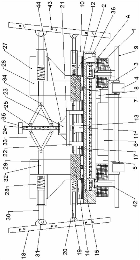
[0028] Such as Figure 1-5As shown, the channel side wall supporting and fixing device for water conservancy construction according to the embodiment of the present invention includes a connecting seat 1, the upper end of the connecting seat 1 is provided with a fixed box 2, and the lower end of the connecting seat 1 is provided with several Universal wheel frame 3, the lower end of the universal wheel frame 3 is movably connected with moving rollers 4, the middle part of the connecting seat 1 is provided with a placement cavity 5, and the inner middle part of the placement cavity 5 is provided with a storage battery 6, so One side of the storage battery 6 is provided with a control device 7, the upper end of the control device 7 is provided with a wireless signal transmission device 8, the lower part of the connecting base 1 is provided with a supporting floor 9, and the interior of the fixed box 2 is provided with a penetrating The connecting seat 1 is a lifting device fixed...
Embodiment 2
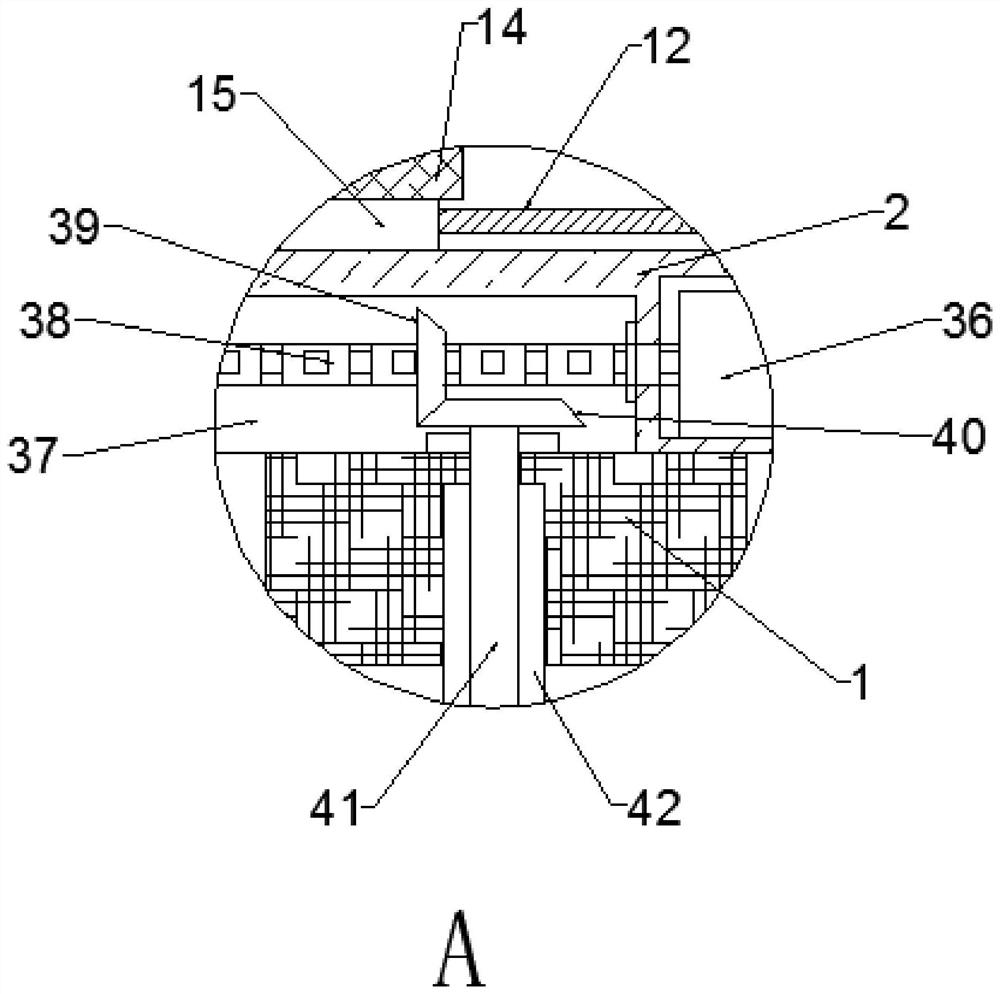
[0030] Such as Figure 1-5 As shown, the lifting device includes a motor two 36 located in the motor cavity at one end of the fixed box 2, a drive cavity 37 is provided in the middle of the lower end of the fixed box 2, and a drive cavity 37 is provided at one end of the motor two 36, and a motor extending to the The rotating screw mandrel 38 in the driving chamber 37, the two ends of the rotating screw mandrel 38 located in the driving chamber 37 are provided with rotating bevel gears 39, and the inner two ends of the driving chamber 37 are provided with rotating The interlocking bevel gear 40 matched with the bevel gear 39, the lower end of the interlocking bevel gear 40 is provided with an adjusting screw 41 that runs through the two ends of the connecting seat 1, and the long grooves at both ends of the connecting seat 1 are provided with The lifting sleeve 42 matched with the adjusting screw rod 41 , the lower end of the lifting sleeve 42 is fixedly connected with the sup...
Embodiment 3
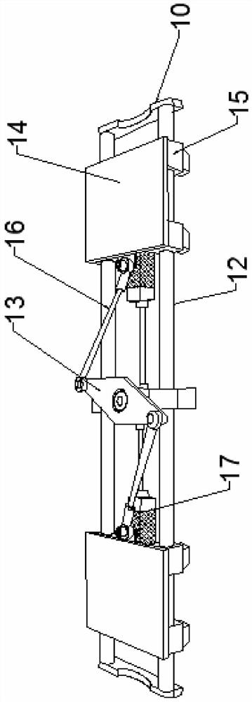
[0032] Such as Figure 1-5 As shown, the bottom end of the sliding cylinder 15 is provided with a dovetail slider, and both sides of the upper middle part of the fixed box 2 are provided with a dovetail chute guide rail matched with the dovetail slider. The support plate 18 is all provided with an inclination sensor 43 connected to the control device 7, and the model of the inclination sensor 43 is ZCT-CX100. The first through hole 28 communicates with the second through hole 29 , and the first through hole 28 and the second through hole 29 form a convex structure. The motor one 23 is connected with the top plate 21 by a motor mount 44, and the sides of the motor mount 44 are all provided with triangular reinforcing plates. The bottom end of the receiving block 27 is an inclined structure, and the connecting structure between the receiving block 27 and the vertical block 26 is integrated. It is not difficult to see from the above-mentioned design that the dovetail slider at ...
PUM
 Abstract
Description
Claims
Application Information
 - R&D Engineer
- R&D Manager
- IP Professional
- Industry Leading Data Capabilities
- Powerful AI technology
- Patent DNA Extraction
Browse by: Latest US Patents, China's latest patents, Technical Efficacy Thesaurus, Application Domain, Technology Topic.
© 2024 PatSnap. All rights reserved.Legal|Privacy policy|Modern Slavery Act Transparency Statement|Sitemap