
Multi-shaft and multi-floating-body wave power generating unit

A generator set and generator technology, which is applied in the direction of ocean energy power generation, electric components, engine components, etc., can solve the problems of affecting the service life of the pump, the rubber ring is not replaced in time, the shutdown of the generator set, etc., and achieves a reliable structure and a good society. Benefits, strong power generation effect

Pending Publication Date: 2020-09-18
长奇(福建)能源科技有限公司
View PDF0 Cites 0 Cited by
  • Summary
  • Abstract
  • Description
  • Claims
  • Application Information

AI Technical Summary

Problems solved by technology

Due to manufacturing reasons, the coaxiality between the pump and the coupling is easy to exceed the standard, and there is a deviation during assembly. As the pump speed increases, the centrifugal force increases the deformation of the coupling, and the large deformation increases the centrifugal force.
Causes a vicious cycle, resulting in vibration and noise, which affects the service life of the pump
In addition, there are other influencing factors such as the coupling pin is loose and not fastened in time, and the rubber ring is worn and not replaced in time.
It can be seen that the hydraulic pump may need to be disassembled during various repairs or routine maintenance, resulting in the shutdown of the entire generator set

Method used


Image

  • Multi-shaft and multi-floating-body wave power generating unit
  • Multi-shaft and multi-floating-body wave power generating unit
  • Multi-shaft and multi-floating-body wave power generating unit

Examples


Embodiment approach

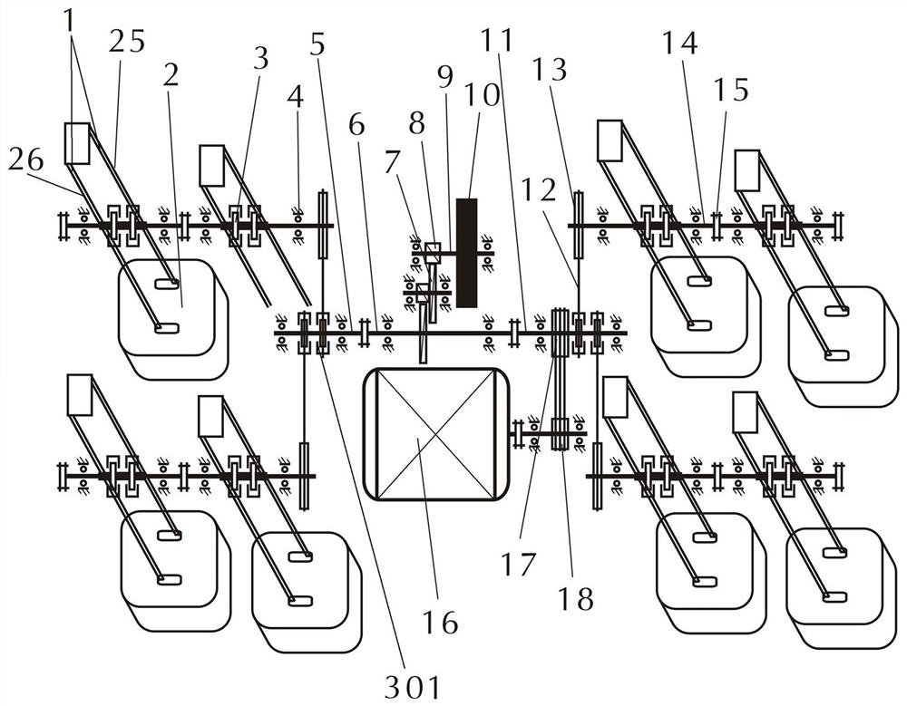
[0041] In summary, and in conjunction with the accompanying drawings, the embodiments of the present invention are:

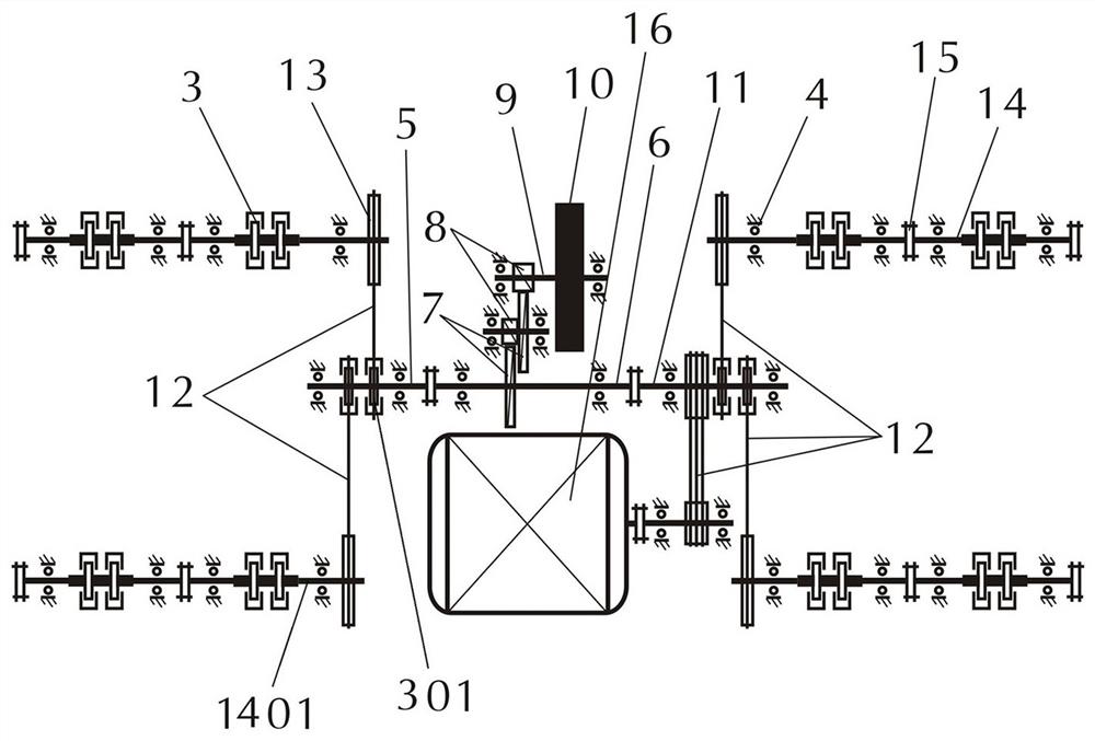
[0042] One, set an intermediate shaft 6 in the generating set,

[0043] a, a B transmission wheel 17 is arranged on one side of the intermediate shaft 6, and the B transmission wheel 17 is connected with the C transmission wheel 18 on the extension shaft of the generator shaft with a transmission belt 12,

[0044] b, a large gear 7 is arranged in the middle of the intermediate shaft 6, and the large gear is meshed with the pinion 8 on the flywheel shaft 9 of a flywheel 10 through a gear set,

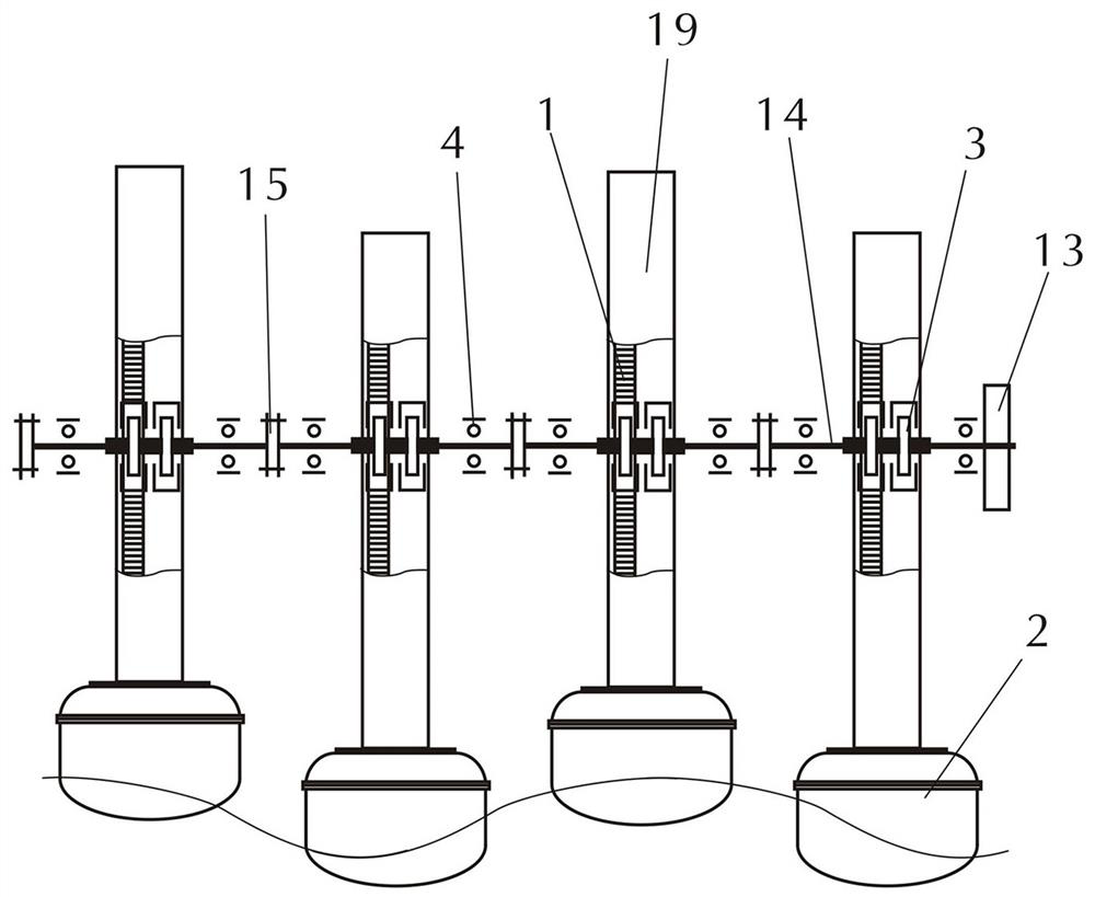
[0045] c, two intermediate shaft overrunning clutches 301 are respectively arranged at both ends of the intermediate shaft 6, and an overrunning clutch combination shaft 14 parallel to the intermediate shaft 6 is arranged at the left and right positions of the axisymmetric sides of the intermediate shaft 6, each overrunning clutch One end of the clutch combination shaft ...


PUM


Abstract

The invention discloses a multi-shaft and multi-floating-body wave power generating unit. A driving wheel B is arranged on an intermediate shaft and is connected with a driving wheel C on the extending shaft of an electric generator through a driving belt; a large gear arranged in the middle of the intermediate shaft is meshed with a flywheel for driving; two intermediate shaft overrun clutches are arranged at each of the two ends of the intermediate shaft; an overrun clutch built-up shaft is arranged on each of left and right positions in the two-side direction of the intermediate shaft; a driving wheel A is arranged at the end, close to the intermediate shaft, of each of the overrun clutch built-up shaft; each of the driving wheels A is connected with a corresponding intermediate shaft overrun clutch through the driving belt; each of the overrun clutch built-up shafts is composed of multiple double-overrun-clutch short shafts; two overrun clutches forming a pair are mounted at the middle of each of the double-overrun-clutch short shafts; two floating body perpendicular shafts of each floating body are distributed at the positions, having the same distance to the two sides of eachof the double-overrun-clutch short shafts; and each of the floating body perpendicular shafts clings to one overrun clutch. The multi-shaft and multi-floating-body wave power generating unit has theadvantages of being reliable in structure and maintained without halt.

Description

technical field [0001] The invention relates to the technical field of wave power generation, in particular to a multi-axis multi-floating body wave power generating set. Background technique [0002] The waves in the ocean have enormous energy. According to the estimation of scientists, the power of the wave energy is as high as 2.0×100,000 kilowatts on the sea surface of 1 square kilometer. If it can be effectively developed and utilized, it will be able to obtain very considerable energy . [0003] The average wave height of my country's Yellow Sea and East China Sea is 1.5 meters, and the annual average wave height of the South China Sea is 1 meter. Many sea areas are suitable for building offshore platforms to provide electricity nearby. The development of sea wave power generation will bring us into a completely natural energy use era. [0004] There are already cases of wave power generation, such as the report "The world's first wave generator has been successfully...

Claims


Application Information

Patent Timeline
Patent Type & Authority Applications(China)
IPC IPC(8): F03B13/18H02K7/18
CPCF03B13/18H02K7/1807F05B2240/95Y02E10/30
Inventor 沈金钟卢立祥
Owner 长奇(福建)能源科技有限公司
Learn More