Eureka AIR delivers breakthrough ideas for toughest innovation challenges, trusted by R&D personnel around the world.

Wave energy efficient pneumatic conversion device and pneumatic conversion method thereof

A technology of conversion device and pneumatic device, which is applied in the direction of using solar energy to generate mechanical power, ocean energy power generation, engine components, etc. Problems such as low efficiency at work points

Active Publication Date: 2020-09-18
BEIHANG UNIV
View PDF9 Cites 2 Cited by
  • Summary
  • Abstract
  • Description
  • Claims
  • Application Information

AI Technical Summary

Problems solved by technology

The randomness and instability of the waves lead to the instability of the pneumatic turbine, and the efficiency of the working point of the turbine is low
Two-way flow of airflow, turbines are generally designed for one-way flow, and reverse flow turbines have low efficiency
The output voltage of wave power generation is unstable in amplitude, frequency and phase, and it will have an impact on the grid when connected to the grid

Method used


Image

  • Wave energy efficient pneumatic conversion device and pneumatic conversion method thereof
  • Wave energy efficient pneumatic conversion device and pneumatic conversion method thereof
  • Wave energy efficient pneumatic conversion device and pneumatic conversion method thereof

Examples


Embodiment

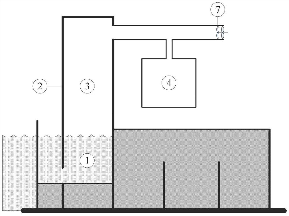
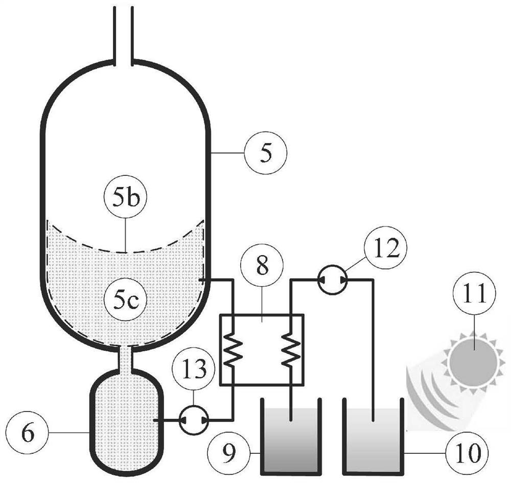
[0040] This embodiment discloses a wave energy efficient pneumatic conversion device, including a column chamber 2, a constant pressure gas storage system 4 and a turbine 7;

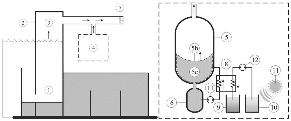
[0041] Specifically, see Figure 1-2 , the column chamber 2 is connected to the turbine 7 through a pipeline, and the constant pressure gas storage system 4 is connected to the pipeline, wherein one side of the column chamber 2 is close to the wall, and the bottom of the other side is provided with a water inlet for completing With the energy conversion of wave energy, at the same time, the interior of the column chamber 2 is divided into a water column 1 and an air column 2. Under the wave fluctuation, the water column 1 floats up and down, and the air column 2 is squeezed to generate airflow, which flows to the constant pressure gas storage system 4 and Turbine 7.

[0042] Only in this embodiment, the constant pressure gas storage system 4 is connected in parallel to the gas circuit connected to the c...


PUM


Abstract

The invention discloses a wave energy efficient pneumatic conversion device controlled by the constant pressure and method. Container storage and gas-liquid phase transition of working substances areutilized to compensate for the air pressure variation of the wave energy efficient pneumatic conversion device, the volatility of energy conversion is reduced, and the efficiency of the pneumatic conversion device is improved. The device includes assemblies of a column type volume cavity, a turbine, an air storage tank, a working substance storage tank, a heat exchanger, and a circulating pump andthe like, and a separator is arranged between air and phase transition working substances to prevent the air from mixing with the phase transition working substances. When the gas column flow in thecolumn type volume cavity is greater than the rated flow in the turbine, the circulating pump drives working substances to penetrate through the heat exchanger to carry out cooling, the working substances change from a gaseous state to a liquid state to discharge from the air storage tank, and the air enters the air storage tank to store. When the gas column flow in the column type volume cavity is less than the rated flow in the turbine, the circulating pump drives the working substances to penetrate through the heat exchanger to carry out heating, the working substances change from a liquidstate to a gaseous state to enter the air storage tank, the air in the air storage tank is discharged, and the turbine pressure remains approximately constant on the condition of wave flow volatility.

Description

technical field [0001] The invention relates to the technical field of renewable energy, and more specifically relates to a wave energy efficient aerodynamic conversion device and an aerodynamic conversion method thereof. Background technique [0002] At present, about 85% of my country's energy consumption comes from the combustion of fossil energy. Problems such as environmental pollution and ecological damage are becoming more and more serious, manifested in excessive air pollution index, increasing carbon emissions, rising temperature and climate warming. my country's energy structure dominated by fossil energy has led to increasingly serious problems such as environmental pollution and ecological damage. The ever-increasing demand for energy and the shortage of fossil energy supply will exacerbate the environmental and energy crises and affect national energy security. [0003] Develop renewable energy to effectively resolve the threat to human survival and social dev...

Claims


Application Information

Patent Timeline
Patent Type & Authority Applications(China)
IPC IPC(8): F03B13/24F03G6/06
CPCF03B13/24F03G6/06Y02E10/30Y02E10/46
Inventor 许未晴李子瑞胡昱蔡茂林石岩王佳
Owner BEIHANG UNIV
Why Eureka
Eureka Blog
Learn More