Novel compressor buffer tank

A technology of compressor and buffer tank, applied in the field of compressor buffer, can solve the problems of poor economic effect, occupying large space, reliability of compressor cylinder, and economical decline, so as to suppress gas pulsation, realize throttling effect, The effect of reducing overall length and volume

Pending Publication Date: 2020-09-18
JEREH OIL & GAS ENG
View PDF0 Cites 105 Cited by
  • Summary
  • Abstract
  • Description
  • Claims
  • Application Information

AI Technical Summary

Problems solved by technology

Some schemes in the prior art generally use increased pipeline support to prevent the pipeline from vibrating significantly, and cannot control the airflow pulsation well, ignoring the influence of the airflow pulsation on the air valve and pipeline of the compressor cylinder, thus Reduce the reliability and econo

Method used


Image

  • Novel compressor buffer tank
  • Novel compressor buffer tank

Examples


Embodiment Construction

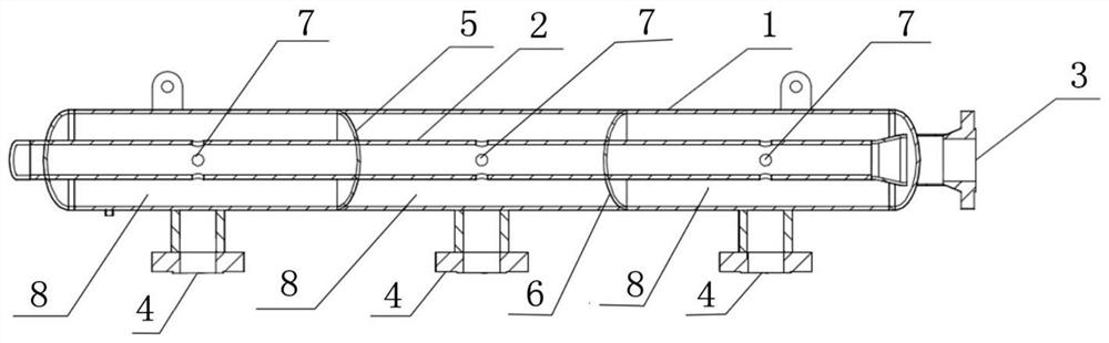
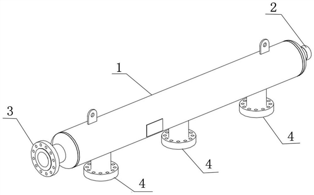
[0018] Such as Figure 1 to 2 As shown, a new type of compressor buffer tank includes a tank body 1, an internal pipe 2, an air inlet 3, an air outlet 4, a first inner head 5, a second inner head 6 and a vent 7, the first inner The head 5 and the second inner head 6 are respectively arranged inside the tank body 1. The first inner head 5 and the second inner head 6 separate the inside of the tank body 1 into three independent chambers 8. The internal pipe 2 is arranged in the tank body 1 and penetrates three chambers 8. The internal pipe 2 of each chamber 8 is provided with a vent 7 and an air inlet 3 is provided at one end of the tank body 1. The port 3 is connected with the internal pipeline 2, and an air outlet 4 is provided on the side wall of the tank 1, and the air outlet 4 is used for discharging the gas in the tank 1. In the buffer tank body 1, an inner head, a gas inner pipe 2 and a vent 7 are opened on the pipe to make the gas form an air inlet 3---internal pipe 2---...


PUM


Abstract

The invention discloses a novel compressor buffer tank. The buffer tank comprises a tank body, an inner pipe, an air inlet, air outlets, a first inner head, a second inner head and air holes, whereinthe first inner head and the second inner head are arranged inside the tank body, and the interior of the tank body is divided into three independent chambers by the first inner head and the second inner head; the inner pipe is arranged in the tank body and penetrates through the three chambers, and the inner pipes of each chamber are provided with the air holes; the air inlet is formed in one endof the tank body, and communicates with the inner pipe; the air outlets are formed in the side wall of the tank body, and used for discharging gas in the tank body. The buffer tank has the beneficialeffects that by changing the flow direction and route of the gas in a new structural form, gas flow pulsation is suppressed, one end, away from the air inlet, of the inner pipe extends out of the tank body, so that the whole length and volume of the buffer tank can be reduced while gas pulsation is suppressed, the inner pipe is supported, and the material cost is also saved.

Description

Technical field [0001] The invention relates to the technical field of compressor buffering, in particular to a novel compressor buffer tank. Background technique [0002] Reciprocating compressors are widely used in the natural gas, petroleum, and chemical industries. The working characteristic of reciprocating compressors is that the suction and exhaust airflow is intermittent and periodic. Therefore, it is inevitable to stimulate the fluid in the inlet and outlet pipelines to show a pulsating state, so The fluid parameters in the tube change periodically with position and time, such as pressure, speed, and density, which is the so-called air flow pulsation. When the airflow pulsating fluid is transported along the pipeline, when it encounters elbows, reducers, branch pipes, valves, blind plates and other components, it will produce an exciting force that changes periodically with time. Affected by the exciting force, the pipeline will Produce mechanical vibration. The source...

Claims


Application Information

Patent Timeline
IPC IPC(8): F04B39/00
CPCF04B39/0055
Inventor 梁志会尹莎张岩贾春辉胡志强初俊林
Owner JEREH OIL & GAS ENG
Why Eureka
Try Eureka